Solar battery module device and method of installing the same

a solar battery and module technology, applied in the direction of heat collector mounting/support, pv power plants, light and heating equipment, etc., can solve the problems of large-scale operations for reconnection, complex installation work, and the possibility of misconnection not being solved, so as to prevent the damage of the solar battery module, improve the safety of installation operations, and reduce the chance of a worker getting on the solar battery module.

Active Publication Date: 2012-03-27
KYOCERA CORP
View PDF30 Cites 47 Cited by
  • Summary
  • Abstract
  • Description
  • Claims
  • Application Information

AI Technical Summary

Benefits of technology

[0028]In the solar battery module device according to the present invention, the solar battery module can be mounted on the installing member and installed on the sloping roof by fixing the installing member on the roof, then fitting the top-side end part serving as one side of the rectangular shape of the solar battery module from the lower side in the sloping direction of the roof in the engagement part of the upper frame in the installing member, and then mounting the fixing cover on the lower frame with the bottom-side end part serving as the opposite side of the rectangular shape of the solar battery module placed on the placing surface of the lower frame to fix the bottom-side end part on the placing surface. Therefore, a plurality of installing members corresponding to a required number of solar battery module devices, for example, are previously fixed on the roof. The solar battery module can be individually mounted on the installing member at an arbitrary position at an arbitrary time.
[0029]Therefore, it is possible to mount the solar battery modules on the installing members in order from the ridge to the edge of eaves of the sloping roof, for example, which was impossible in the conventional solar battery module device installed in the same manner as the normal roofing material. The chances that a worker must get on the solar battery module can be significantly reduced to improve the safety of installation operations and prevent the solar battery module from damage by suitably setting the order in which the solar battery modules are mounted in conformity with the shape or the like of the roof.
[0030]Furthermore, the solar battery module at the arbitrary position can be individually removed from the installing member in a procedure opposite to the foregoing procedure without removing the other solar battery modules. Therefore, operations in a case where misconnection is found in a test during or after installation, for example, or a case where a failure or the like is found at the time of maintenance and inspection operations of the photovoltaic power generating system can be also significantly simplified.
[0031]When the lower frame in the installing member has the flat plate-shaped extended part extended in a slopingly downward direction of the surface of the solar battery module to be mounted on the lower side in the sloping direction of the roof, and the fixing cover has the flat plate-shaped mounting part overlapped with the extended part and mounted thereon and the fixing part abutted against the end surface and the upper surface of the bottom-side end part of the solar battery module for fixing the bottom-side end part to the lower frame with the mounting part mounted on the extended part, the solar battery module can be mounted on the installing member more reliably without producing backlash or the like.
[0032]That is, when the mounting part of the fixing cover is mounted on the extended part extended in a slopingly downward direction of the surface of the solar battery module of the lower frame with the fixing part of the fixing cover abutted against the end surface and the upper surface of the bottom-side end part of the solar battery module, a fixing force directed downward in the thickness direction, i.e., toward the placing surface of the lower frame can be applied to the bottom-side end part of the solar battery module from the upper surface thereof, and a fixing force directed toward the upper side in the sloping direction of the roof, i.e., toward the upper frame can be also applied to the end part from the end surface thereof.
[0033]Therefore, the solar battery module mounted on the installing member can be prevented from backlash of the solar battery module and more reliably mounted, for example. The deterioration of the solar battery module due to the occurrence of corrosion, for example, can be reliably prevented by preventing a protective film such as an alumite layer, a plating layer, or a clear coat layer for covering a surface of a frame formed of an aluminum alloy or the like, of the solar battery module from damage and chipping and thinning due to backlash of the solar battery module against the installing member, for example.

Problems solved by technology

Therefore, installation work is complicated because it involves a large number of man-hours.
Thus, the problem that misconnection may happen is not still solved.
When misconnection is found during installation or in a test after installation, for example, the roofing materials and the solar battery module devices must be successively removed from the ridge in order, so that there lies a problem that large-scale operations for reconnection are required.
Therefore, there lies a problem that large-scale operations are required for replacing and repairing the failed solar battery module device.
However, a surface of the solar battery module is covered with glass or the like and is slippery, as previously described, so that there lies a problem that the operations cannot be performed safely.
Further, the solar battery module may be damaged by the worker getting thereon.

Method used


Image

  • Solar battery module device and method of installing the same
  • Solar battery module device and method of installing the same
  • Solar battery module device and method of installing the same

Examples


Embodiment Construction

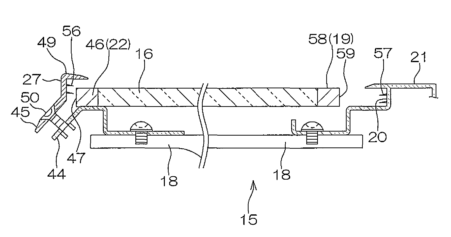
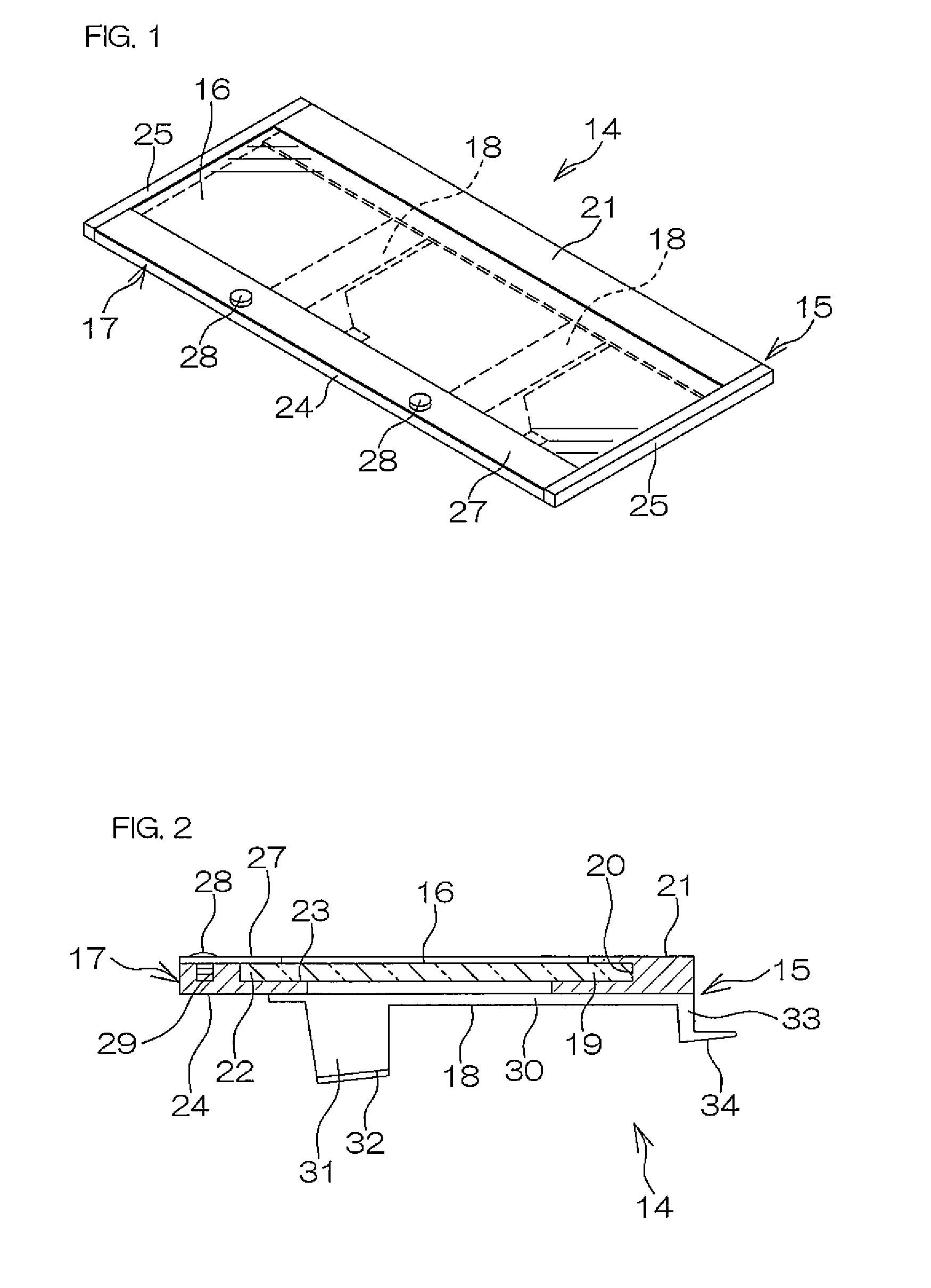
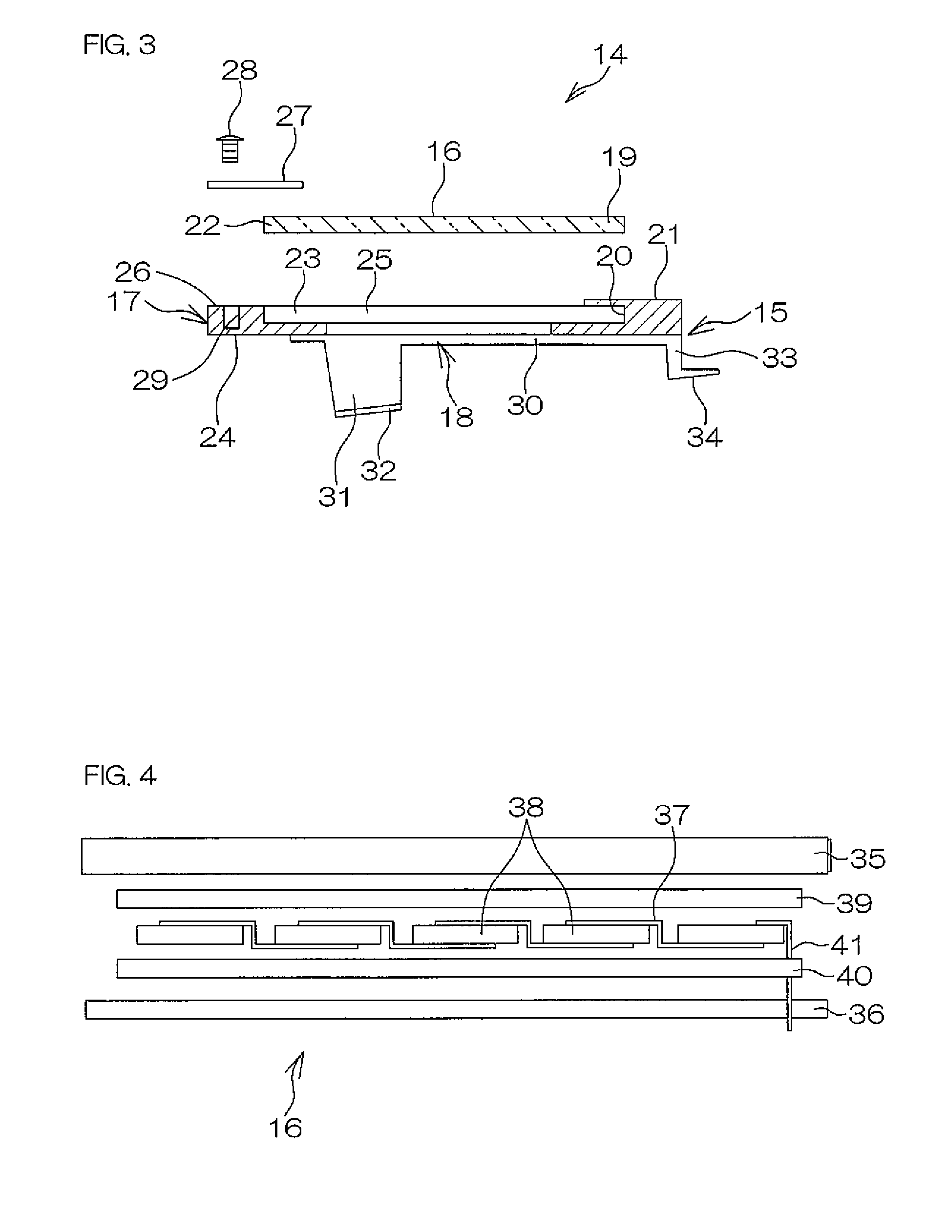
[0135]FIG. 1 is a perspective view showing an example of an embodiment of a solar battery module device 14 according to the present invention. FIG. 2 is a cross-sectional view of the solar battery module device 14 in the example shown in FIG. 1. FIG. 3 is an exploded sectional view of the solar battery module device 14 in the example shown in FIG. 1. FIG. 5 is a cross-sectional view showing one step in construction for constructing a photovoltaic power generating system of a roof-integration type by installing the solar battery module device 14 in the example shown in FIG. 1 on a roofer 7 of a sloping roof. A black arrow in the figure indicates the sloping direction of the roofer 7. In the figure, the left side is the lower side, and the right side is the upper side in the sloping direction. The same applies to FIGS. 6 and 7. FIG. 8 is a perspective view of an installing member 15 in the solar battery module device 14 in the example shown in FIG. 1.

[0136]Referring to FIGS. 1, 2, and...


PUM


Abstract

A solar battery module device (14), wherein an bottom-side end part (22) is fixed onto a placing surface (23) by fitting the top-side end part (19) as one-side of a rectangular shape of a rectangular flat plate-like solar battery module (16) to the engagement part (20) of an upper frame (21) forming a frame (17) from the lower side of a roofer and by fitting a fixing cover (27) to a lower frame (24) in a state in which the bottom-side end part (22) as the opposite-side of the rectangular shape of the solar battery module (16) is placed on the placing surface (23) of the lower frame (24) forming the frame (17). According to the solar battery module device of the present invention, operations such as installation work and maintenance and inspections for the device can be easily and safely performed without damaging the solar battery module (16).

Description

TECHNICAL FIELD[0001]The present invention relates to a solar battery module device for installing a solar battery module on a roof that generates power utilizing solar energy and a method of installing the same.RELATED ART[0002]By recent rise in environmental consciousness, photovoltaic power generating systems for generating power by installing solar battery modules on roofs of general housings and public buildings have been attracting attention to as clean energy. Example of a photovoltaic power generating system installed on an sloping roof of a general housing or the like include a roof-placement type system for installing a mount on the existing roof and mounting a solar battery module thereon and a roof-integration type system in which a roof is thatched with a roofing material such as a roof tile or a slate having a solar battery incorporated therein in place of or together with a normal roofing material.[0003]The latter photovoltaic power generating system of a roof-integra...

Claims


Application Information

Patent Timeline
Patent Type & Authority Patents(United States)
IPC IPC(8): E04D13/18
CPCF24J2/465F24J2/5211F24J2/5235F24J2/5254H02S20/23E04D2001/3458F24J2002/5281Y02B10/12Y02B10/20Y02E10/47F24J2002/5284F24J2002/0061F24S25/632F24S2025/016F24S80/70F24S25/15F24S2025/014F24S25/20F24S2020/13Y02E10/50Y02B10/10E04D1/29
Inventor MASUDA, HIROTOTAKAHASHI, FUTOSHIOHNO, TOSHIAKI
Owner KYOCERA CORP
Why Eureka
Try Eureka