High efficiency refraction body

a refraction body, high efficiency technology, applied in the direction of instruments, lighting and heating apparatus, semiconductor devices for light sources, etc., can solve the problem that the refraction angle of such designs is not wide enough to have a refraction, and achieve the effect of wide illumination, high efficiency and high efficiency

Inactive Publication Date: 2012-03-27
TAIWAN GIGANTIC LIGHT ELECTRIC ,
View PDF6 Cites 10 Cited by
  • Summary
  • Abstract
  • Description
  • Claims
  • Application Information

AI Technical Summary

Benefits of technology

[0003]Accordingly, the primary object of the present invention is to provide a high efficiency refraction body capable of total reflecting and substantially refracting lights from its light source so as to have a wider illumination.
[0004]Another object of the present invention is to provide a high efficiency refraction body having a good lateral illumination for various applications of illumination.
[0005]Through the high efficiency refraction body, lights from its light source will be total reflected and substantially refracted by the surfaces. While a LED light source is arranged to the high efficiency refraction body, lights from the LED light source will be total reflected through a main refraction surface and refracted through a first refraction surface and a second refraction surface so as to be projected through a lateral of the high efficiency refraction body uniformly. An illumination area is increased and a visibility is also improved. Comparing to straight projection of a prior LED lamp device, the present invention can provide more lateral illumination so that the present invention can be applied to various devices such as desk lamp, floor lamp, chandelier, plywood lamp, decorative lamp, or other light sources.

Problems solved by technology

However, the refraction angle of such design is not wide enough to have a refraction larger than 180 degrees.

Method used


Image

  • High efficiency refraction body
  • High efficiency refraction body
  • High efficiency refraction body

Examples


Embodiment Construction

[0014]In order that those skilled in the art can further understand the present invention, a description will be provided in the following in details. However, these descriptions and the appended drawings are only used to cause those skilled in the art to understand the objects, features, and characteristics of the present invention, but not to be used to confine the scope and spirit of the present invention defined in the appended claims.

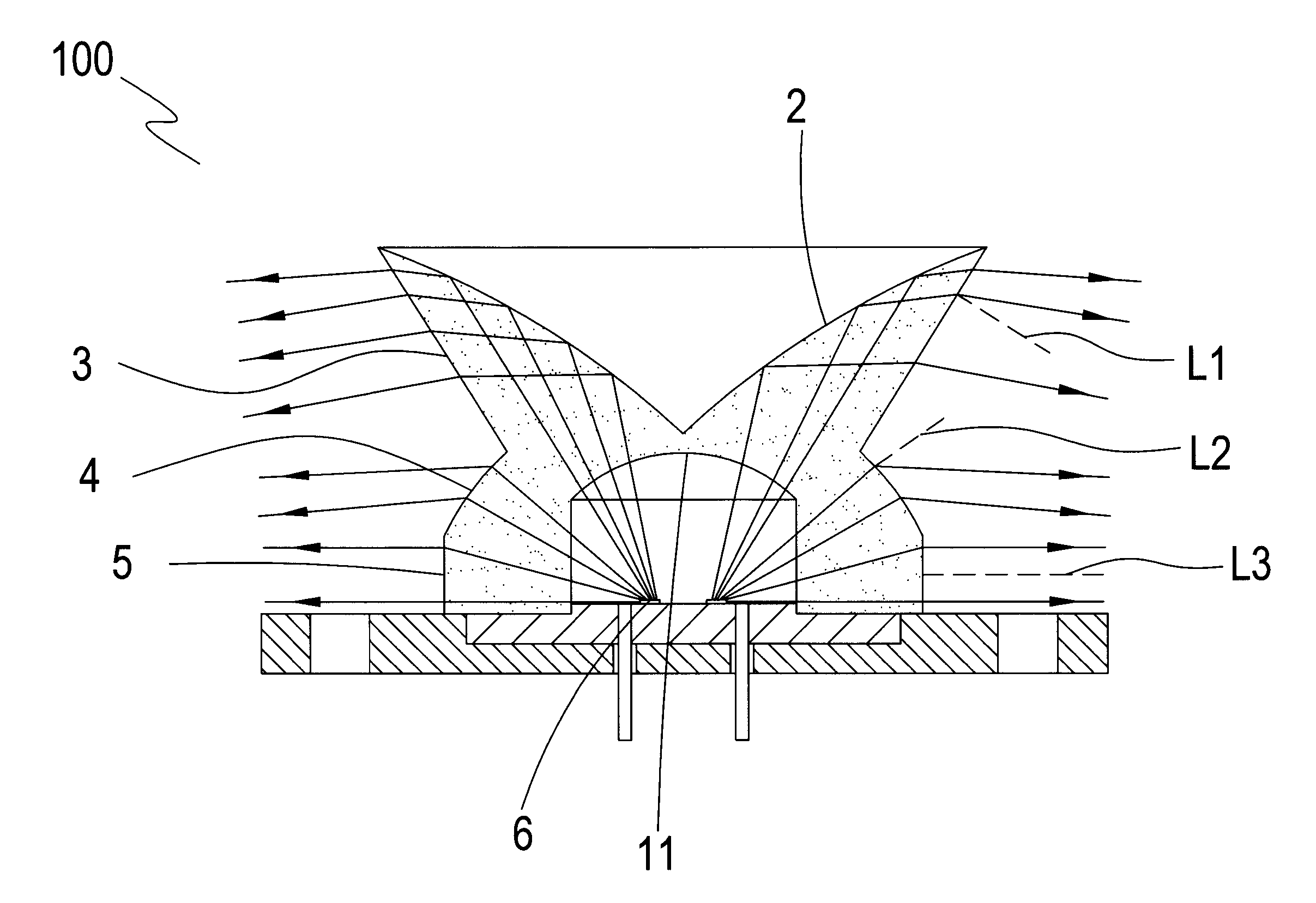
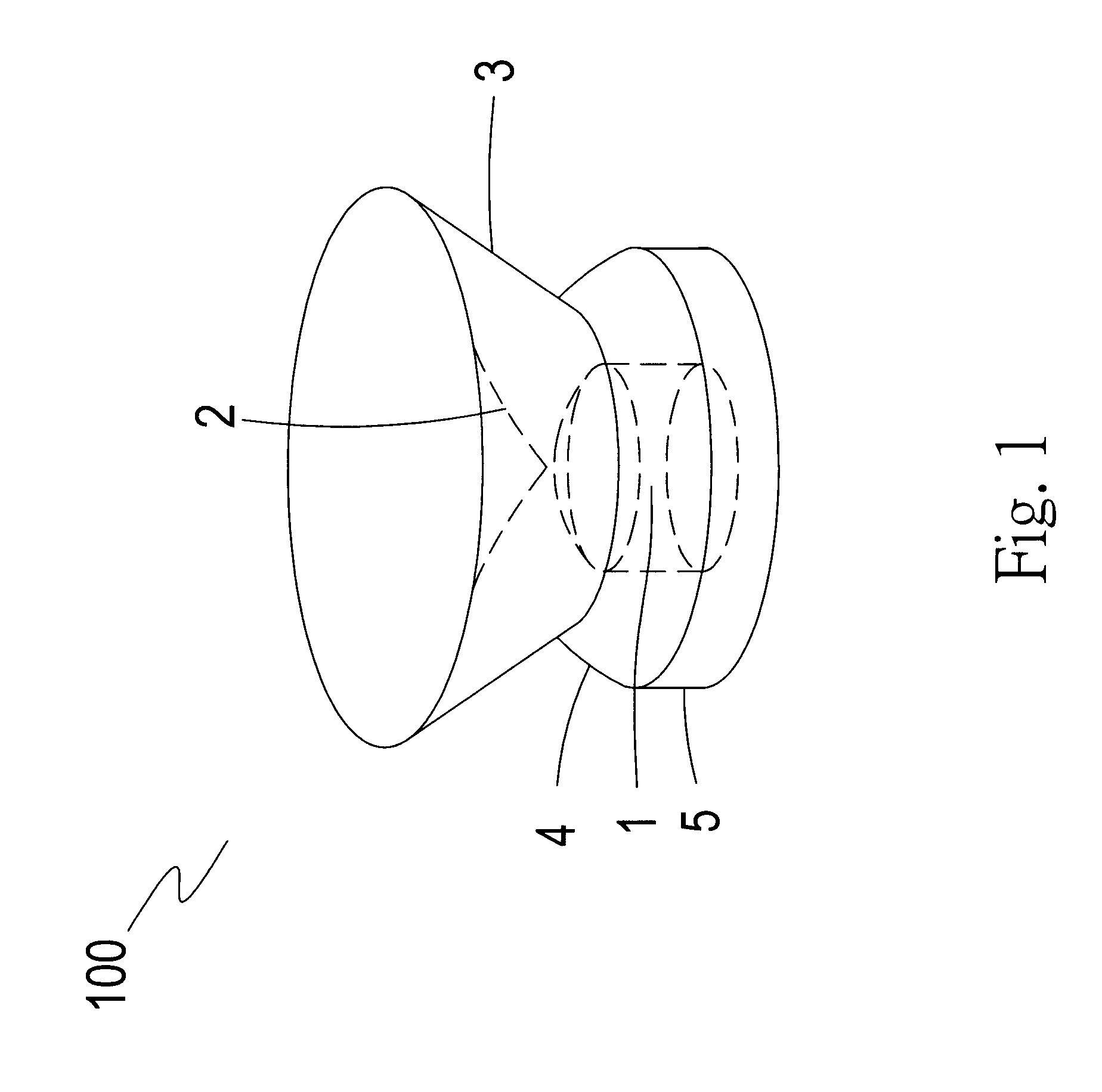
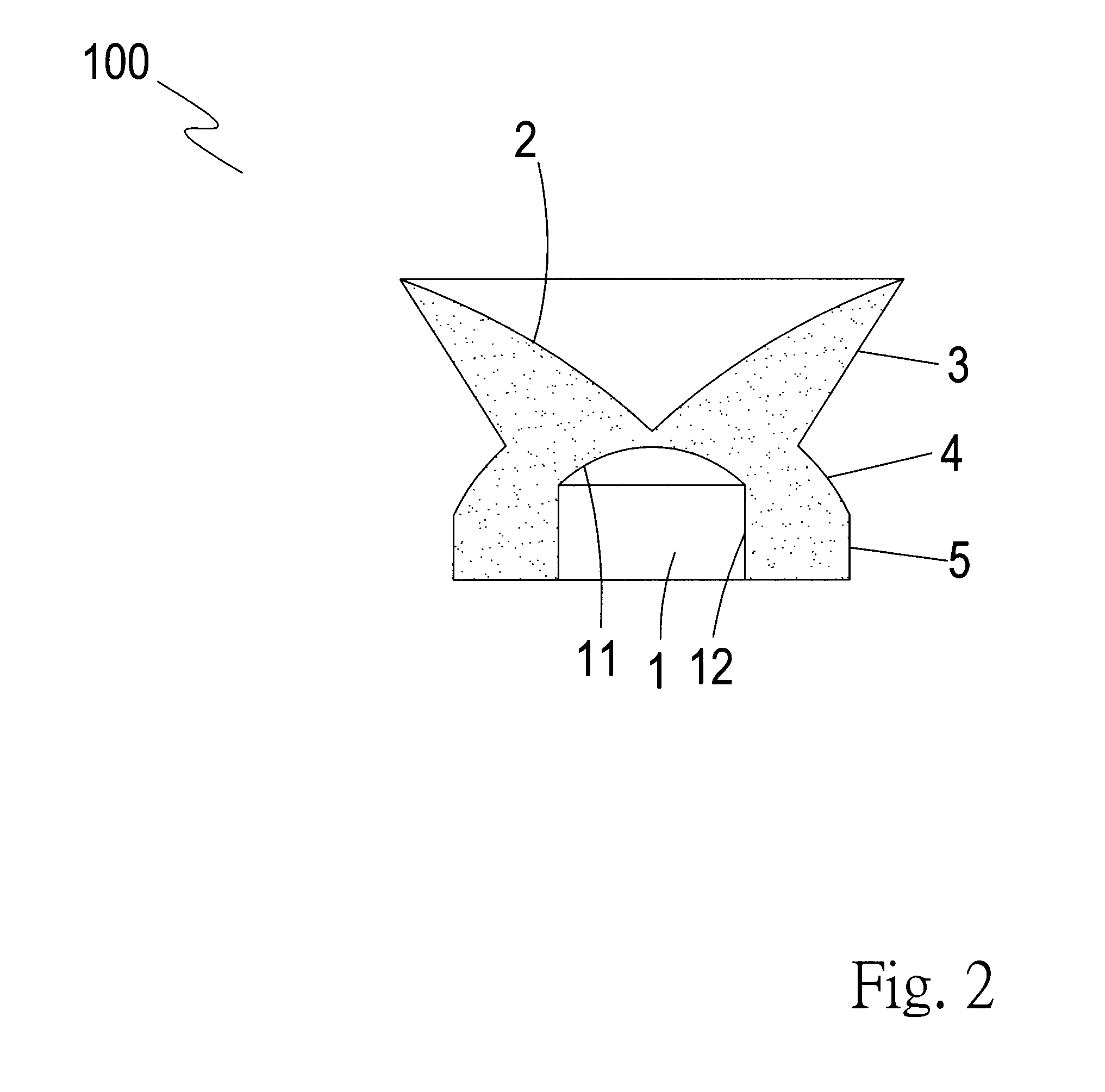
[0015]Referring to FIGS. 1 and 2, a high efficiency refraction body 100 according to present invention has a light source chamber 1 and a main refraction surface 2. The light source chamber 1 for receiving a light source has a transmission surface 11 on a top of the light source chamber 1 and an inner wall 12 around the light source chamber 1. The transmission surface 11 is pervious to light. The main refraction surface 2 is formed above the light source chamber 1 and the cross section of the main refraction surface is approximately a shape of a V....


PUM


Abstract

A high efficiency refraction body includes a light source chamber and a main refraction surface opposite to the light source chamber. A first refraction surface and a second refraction surface for refracting the lights are formed to a peripheral of the high efficiency refraction body. A light source is received to the light source chamber. Lights from the light source will be total reflected because the incident angles of the lights exceed a critical angle of the main refraction surface. The reflected lights will be refracted through the first refraction surface and the second refraction surface so as to pass a lateral of the refraction body. A uniform lateral illumination of the refraction body will correct the poor lateral illumination of LED light devices.

Description

FIELD OF THE INVENTION[0001]The present invention relates to refraction body, and particular to a high efficiency refraction body capable of total reflecting and substantially refracting lights from its light source.DESCRIPTION OF THE PRIOR ART[0002]Prior LED lamp devices include a metal cup body and a guiding component. The guiding component has a curved surface on an inner surface of an upper end thereof and an inclined surface on a peripheral of a lower end thereof. Such devices can be applied to alarm lamp, alarm lamp on police patrol car, alarm lamp for tall building, or guiding signal for airport runway. Refraction bodies of such devices are located to the focus points of the curved surfaces of the metal reflection cup body. The dizzy light of the LED will be eliminated through the assembly. However, the refraction angle of such design is not wide enough to have a refraction larger than 180 degrees.SUMMARY OF THE PRESENT INVENTION[0003]Accordingly, the primary object of the pr...

Claims


Application Information

Patent Timeline
Patent Type & Authority Patents(United States)
IPC IPC(8): F21V5/00
CPCF21V7/0091G02B19/0028G02B19/0061F21Y2101/02H01L33/58F21Y2115/10
Inventor LI, CHIA-MAO
Owner TAIWAN GIGANTIC LIGHT ELECTRIC ,
Why Eureka
Try Eureka