Control drive with electric motor and planetary gear mechanism

a technology of planetary gear mechanism and control drive, which is applied in the direction of differential gearing, dynamo-electric machines, applications, etc., can solve the problems of light play between the gears, and achieve the effect of reducing the frequency of assembly errors, facilitating self-alignment of the planet gears, and increasing assembly speed

Inactive Publication Date: 2012-03-27
BUHLER MOTOR GMBH
View PDF11 Cites 4 Cited by
  • Summary
  • Abstract
  • Description
  • Claims
  • Application Information

AI Technical Summary

Benefits of technology

[0006]This task is accomplished according to the present invention in that the axial spacing (A1) between the front surface (7a) of the first planet gear (6a) and the first angle area (8a) of the ring gear (4) assigned to it differs from the axial spacing (A2) between the front surface (7b) of the second planet gear (6b) and the second angle area (8b) of the ring gear (4) assigned to it. Through this arrangement, the individual planet gears enter the assembly-critical tooth area of the ring gear independently of each other during the time of assembly, so that easier self-alignment of the planet gears is possible. This increases the assembly speed and reduces the frequency of errors during assembly. The invention can be applied to planetary gear mechanisms with two or more planet gears in the same gear stage.

Problems solved by technology

Ordinarily during assembly, angle inaccuracies can occur leading to there being slight play among the gears.

Method used


Image

  • Control drive with electric motor and planetary gear mechanism
  • Control drive with electric motor and planetary gear mechanism
  • Control drive with electric motor and planetary gear mechanism

Examples


first embodiment

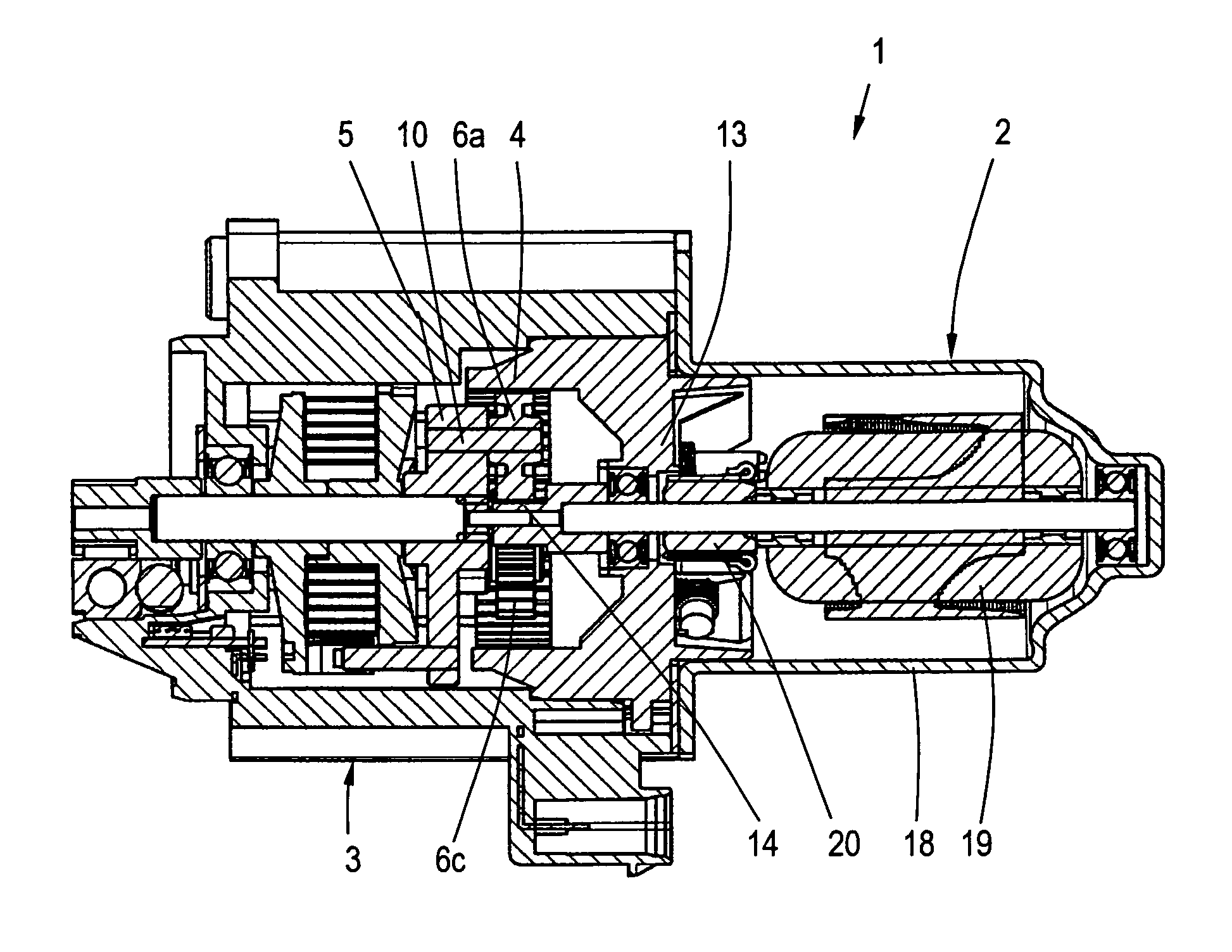
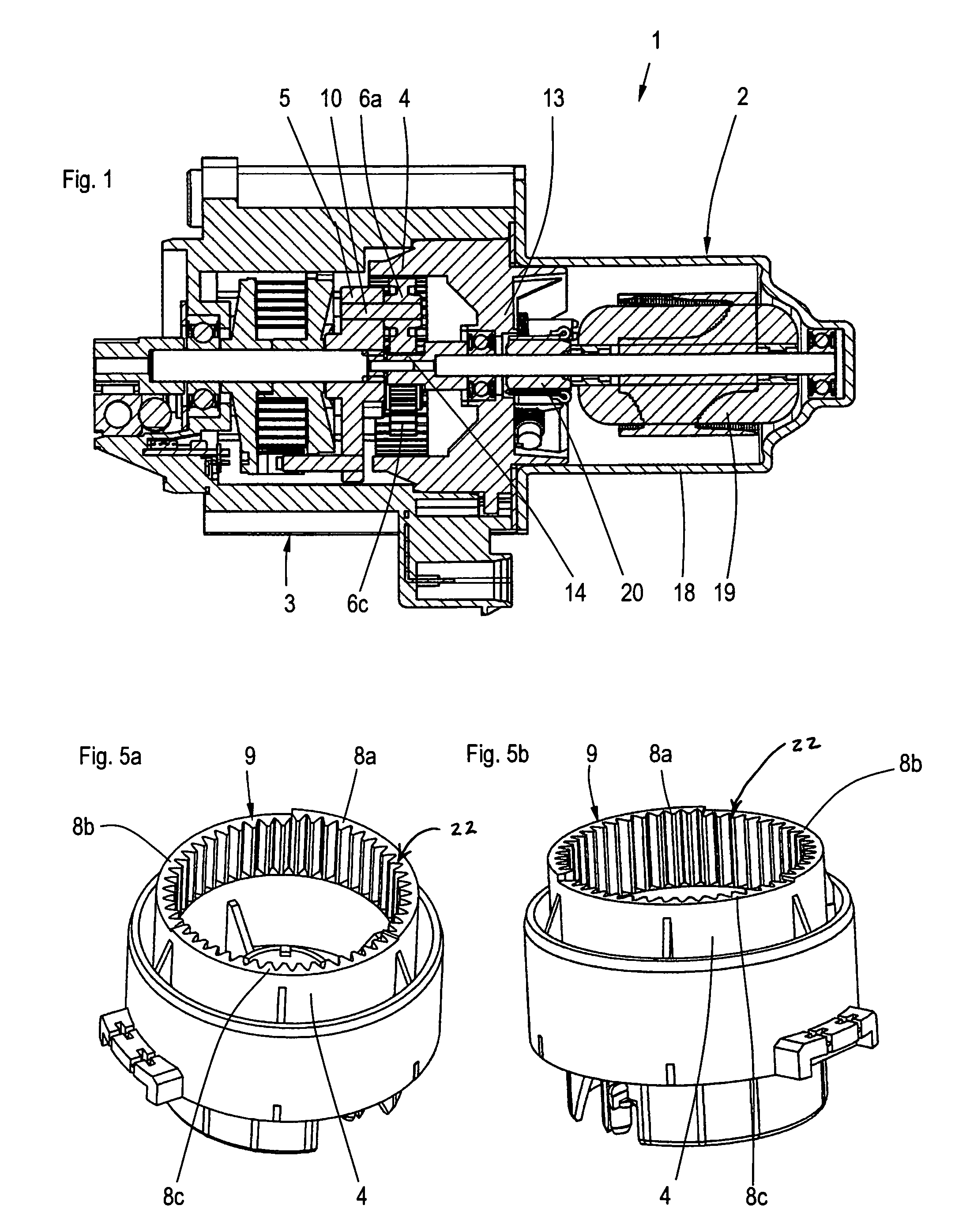
[0024]According to the invention, the planet gears (6a, 6b, 6c) have different thicknesses in the axial direction. Time sequencing during assembly can therefore be achieved. However, a drawback is that different individual parts are necessary. In addition, this solution might lead to undesired noise at higher speeds, for which reason this embodiment is not preferred.

second embodiment

[0025]A second embodiment is characterized by the fact that the planet gears (6a, 6b, 6c) are mounted in different axial arrangements on the planet carrier (5), the planet gears having the same shape. Time decoupling of the engagement time of the planet gears is also achieved with this solution. Only one component must be changed, depending on the design of the planet carrier.

[0026]A drawback in the two embodiments just mentioned is also the axial mounting of the planet carrier in the installed state. This must occur on the planet carrier itself, because a contact surface in the ring gear or gear housing would require either an additional component or large axial play would have to be tolerated in at least two planet gears.

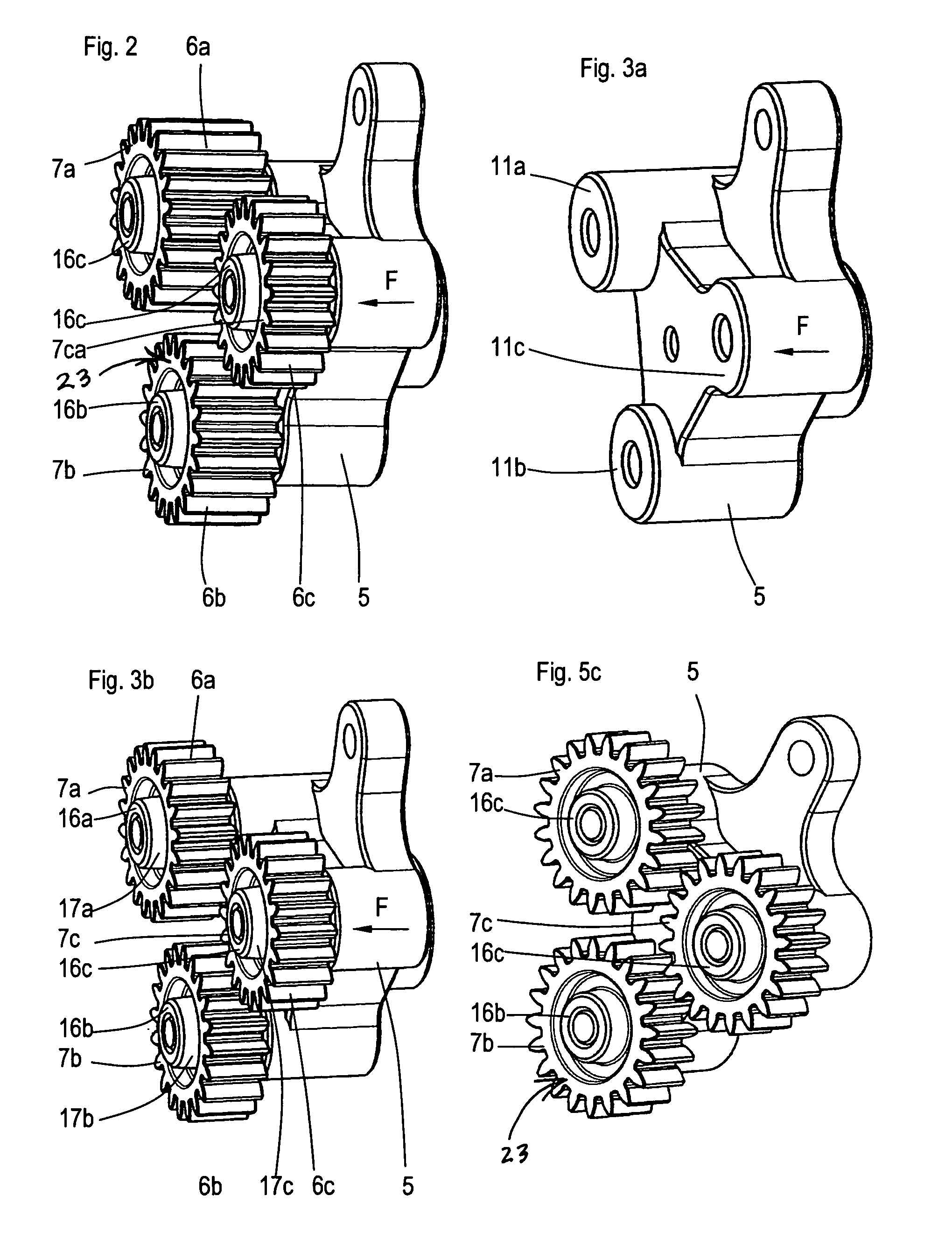
[0027]In order to implement the second embodiment, the planet carrier (5) has stud axles (10a, 10b, 10c), on which the planet gears (6a, 6b, 6c) are radially mounted, and the planet carrier (5) has stationary seat surfaces (11a, 11b, 11c), on which the planet gear...

third embodiment

[0028]In the invention, it is proposed that the front surfaces (7a, 7b, 7c) of the planet gears (6a, 6b, 6c) be arranged in different axial positions in the assembled state, the planet gears (6a, 6b, 6c) having the same tooth width and stationary seat surfaces (15a, 15b, 15c or 16a, 16b, 16c) axially protruding on both sides of the teeth of planet gears (6a, 6b, 6c) to different extents. The ring gears are designed in one piece with hubs or connected by press-fit, the ring gears being arranged axially offset to different extents relative to the hub. With the planet gears assembled, identical parts can be used and the desired geometry achieved merely by different press-fit heights.

[0029]For the first and third planet gears (6a, 6c), they can be identically designed, being merely rotated by 180°, in order to achieve a different axial offset. The second planet gear (6b) differs from the first and third planet gears, but can be shaped symmetrically to a center plane and therefore mounte...


PUM

PropertyMeasurementUnit
rotationaaaaaaaaaa
symmetryaaaaaaaaaa
areaaaaaaaaaaa

Abstract

A control drive, consisting of an electric motor and a planetary gear mechanism flush with the electric motor on the same axis of symmetry, comprising a ring gear, a planet carrier and three planet gears mounted on the planet carrier, the planet gears each having a front surface in the assembly direction in the area of their external teeth and the ring gear in the region of its internal teeth having three angle areas assigned to the planet gears of its end opposite the assembly direction in a defined angle position of the planet carrier to ring gear. The task of the present invention is to ensure that an economical and time-decoupled simple and rapid assembly of the three planet gears in the ring gear is possible without increasing the manufacturing expense on this account, in which only slight changes to existing forms are necessary. This task is solved in that the axial spacing between the front surface of the first planet gear and the first angle area of ring gear assigned to it differs from the axial spacing between the front surface of the second planet gear and the second angle area of ring gear assigned to it and the axial spacing between the front surface of the third planet gear and the third angle area of ring gear assigned to it.

Description

BACKGROUND OF THE INVENTION[0001]1. Field of the Invention[0002]The invention concerns a control drive, consisting of an electric motor and a planetary gear mechanism, comprising a ring gear, a planet carrier and several planet gears mounted on the planet carrier, the planet gears each having a front surface in the assembly direction F in the region of their external teeth, and the ring gear having, in the region of its internal teeth, several angle areas assigned to the planet gears of the end opposite the assembly direction F in a defined angle position of the planet carrier to ring gear.[0003]2. Description of Related Art[0004]A generic control drive is described in DE 197 29 988 C1, in which the angle areas of the end opposite the assembly direction are arranged in a single plane and the ends of the planet gears in front in the assembly direction are also arranged in a single plane, so that the individual spacings between the ends of the planet gears and the angle areas of the r...

Claims


Application Information

Patent Timeline
Patent Type & Authority Patents(United States)
IPC IPC(8): F16H48/06B21D53/28F16H57/023
CPCF16H57/08H02K7/116F16H57/082F16H57/023Y10T29/49464F16H2055/176
Inventor GUTTENBERGER, RICHARDSCHREIBER, THOMAS
Owner BUHLER MOTOR GMBH
Why Eureka
Try Eureka