
A kind of igbt structure with built-in diode and its manufacturing method

A technology with built-in diodes and manufacturing methods, applied in diodes, semiconductor/solid-state device manufacturing, transistors, etc., can solve problems such as expensive, and achieve the effects of enhancing stability, optimizing device performance, and uniform distribution

Active Publication Date: 2016-12-21
BYD SEMICON CO LTD
View PDF3 Cites 0 Cited by
  • Summary
  • Abstract
  • Description
  • Claims
  • Application Information

AI Technical Summary

Problems solved by technology

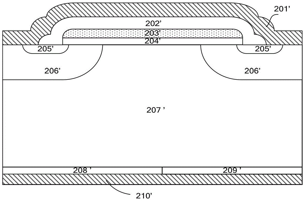
[0006] The purpose of the present invention is to at least solve one of the above-mentioned technical defects, especially to solve the problem that the back structure and the front structure of an IGBT with a built-in diode need to be aligned using an expensive double-sided photolithography machine, and to provide an IGBT with a built-in diode The IGBT structure and its manufacturing method, using a single-sided photolithography machine to complete the self-alignment of the back structure and the front structure of the wafer, and improve the stability of the device

Method used


Image

  • A kind of igbt structure with built-in diode and its manufacturing method
  • A kind of igbt structure with built-in diode and its manufacturing method
  • A kind of igbt structure with built-in diode and its manufacturing method

Examples


Embodiment 1

[0055] Figure 5-6 It is a structural cross-sectional view of the intermediate steps of the method for forming p-type and n-type strip-shaped doped regions on the back of the wafer according to Embodiment 1 of the present invention. Such as Figure 5-6 As shown, step S3 includes:

[0056] Step S311: Form a patterned first mask layer 110 on the back side 200 of the wafer 300, the first mask layer 110 covers the area of ​​the back side 200 preset as a p-type strip-shaped doped region, such as Figure 5 shown.

[0057] Step S312: performing p-type doping on the back surface 200 of the wafer 300, such as Figure 5 shown.

[0058] Step S313: removing the first mask layer 110 to form p-type strip-shaped doped regions 2 and n-type strip-shaped doped regions 3, such as Figure 6 shown.

Embodiment 2

[0060] Figure 7-9 It is a structural cross-sectional view of the intermediate steps of the method for forming p-type and n-type strip-shaped doped regions on the back of the wafer according to Embodiment 2 of the present invention. Such as Figure 7-9 As shown, step S3 includes:

[0061] Step S321: Perform n-type doping on the back surface 200 of the wafer 300, such as Figure 7 shown.

[0062] Step S322: Forming a patterned second mask layer 111 on the back side 200 of the wafer 300, the second mask layer 111 covers the area of ​​the back side 200 preset as an n-type strip-shaped doped region, such as Figure 8 shown.

[0063] Step S323: performing p-type doping on the back side 200 of the wafer 300, so that the exposed back side 200 region is reversed to p-type doping, such as Figure 8 shown.

[0064] Step S324: removing the second mask layer 111 to form p-type strip-shaped doped regions 2 and n-type strip-shaped doped regions 3, such as Figure 9 shown.

Embodiment 3

[0066] Figure 10-12 It is a structural cross-sectional view of the intermediate steps of the method for forming p-type and n-type strip-shaped doped regions on the back of the wafer according to the third embodiment of the present invention. Such as Figure 10-12 As shown, step S3 includes:

[0067] Step S331: performing p-type doping on the back surface 200 of the wafer 300, such as Figure 10 shown.

[0068] Step S332: Form a patterned third mask layer 112 on the back side 200 of the wafer 300, the third mask layer 112 covers the area of ​​the back side 200 preset as a p-type strip-shaped doped region, such as Figure 11 shown.

[0069] Step S333: Perform n-type doping on the back side 200 of the wafer 300, so that the exposed back side 200 region is reversed to n-type doping, such as Figure 11 shown.

[0070] Step S334: removing the third mask layer 112 to form p-type strip-shaped doped regions 2 and n-type strip-shaped doped regions 3, such as Figure 12 shown.


PUM


Abstract

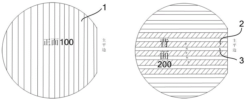
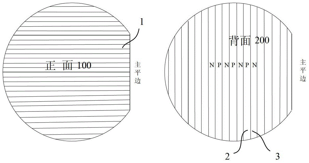
The invention provides an IGBT (insulated gate bipolar transistor) structure with built-in diodes and a method for manufacturing the IGBT structure. The IGBT structure and the method have the advantages that strip-shaped cell regions are formed on the front surface of a semiconductor substrate, type-p strip-shaped doped regions and type-n strip-shaped doped regions which are alternately and parallelly arranged are formed on the back surface of the semiconductor substrate, and the front-surface strip-shaped cell regions are perpendicular to the back-surface type-p strip-shaped doped regions and back-surface type-n strip-shaped doped regions, so that a back-surface structure and a front-surface structure of a wafer can be conveniently and automatically aligned with each other by a single-side lithography machine; width proportions of the type-p strip-shaped doped regions to the type-n strip-shaped doped regions can be adjusted, so that the performance of a device can be optimized; the IGBT structure with the built-in diodes in an embodiment of the invention is structurally distributed uniformly, so that currents, power consumption, temperatures and the like of the device can be distributed uniformly when the device works, and the stability of the device can be improved.

Description

technical field [0001] The invention relates to the technical field of semiconductor design and manufacture, in particular to an IGBT (Insulated Gate Bipolar Transistor) structure with a built-in diode and a manufacturing method thereof. Background technique [0002] IGBT combines the advantages of power MOSFET (Metal-Oxide-Semiconductor-Field-Effect-Transistor, Metal-Oxide-Semiconductor Field-Effect Transistor) and power transistor, with high operating frequency, simple control circuit, high current density, and low on-state voltage. , are widely used in the field of power control. In practical applications, IGBT is rarely used as an independent device, especially under the condition of inductive load, IGBT needs a fast recovery diode freewheeling. Therefore, the existing IGBT products generally use a diode connected in anti-parallel to play the role of freewheeling and protect the IGBT. [0003] In order to reduce the cost, the anti-parallel diode can be integrated in th...

Claims


Application Information

Patent Timeline
Patent Type & Authority Patents(China)
IPC IPC(8): H01L29/06H01L29/739H01L27/06H01L21/331
CPCH01L27/0664H01L29/0657H01L29/66333H01L29/7398
Inventor 肖秀光刘鹏飞吴海平
Owner BYD SEMICON CO LTD
Learn More