Manufacturing method of cable connector assembly

A cable connector and manufacturing method technology, applied in the field of cable connector assembly manufacturing, can solve problems such as uneven pressure, unevenness, shrinkage, and reduce the defect rate, uniform structure distribution, and volume reduction. Effect

Active Publication Date: 2019-08-09
DEYI PRECISION ELECTRONIC IND CO LTD PANYU
View PDF2 Cites 5 Cited by
  • Summary
  • Abstract
  • Description
  • Claims
  • Application Information

AI Technical Summary

Problems solved by technology

However, since the second insulator has to cover multiple components such as the male head, the first insulator, the metal shell, and the cable, the volume of the second insulator must be very large, and the pressure during plastic injection is prone to occur during the injection molding process. Inhomogeneity, so that the second insulating part will eventually have the problems of lack of glue, shrinkage and uneven thickness; at the same time, since the second insulating part is only molded by one-time injection molding, when performing the molding step of the second insulating part, the mold It is necessary to have thimbles against the upper and lower surfaces of the metal shell for positioning. Therefore, after forming the second insulating part, there must be a through hole on the upper and lower surfaces of the second insulating part for the thimble to be pulled out, and the existence of the through hole will make The metal shell is exposed to the outside air, and long-term use will affect the electrical performance and service life of the cable connector assembly; in addition, the lack of glue, uneven thickness and the existence of through holes will affect the user's ability to plug and unplug the cable connector Feel when assembling

Method used


Image

  • Manufacturing method of cable connector assembly
  • Manufacturing method of cable connector assembly
  • Manufacturing method of cable connector assembly

Examples


Embodiment Construction

[0036] In order to facilitate a better understanding of the purpose, structure, features, and effects of the present invention, the present invention will now be further described in conjunction with the accompanying drawings and specific embodiments.

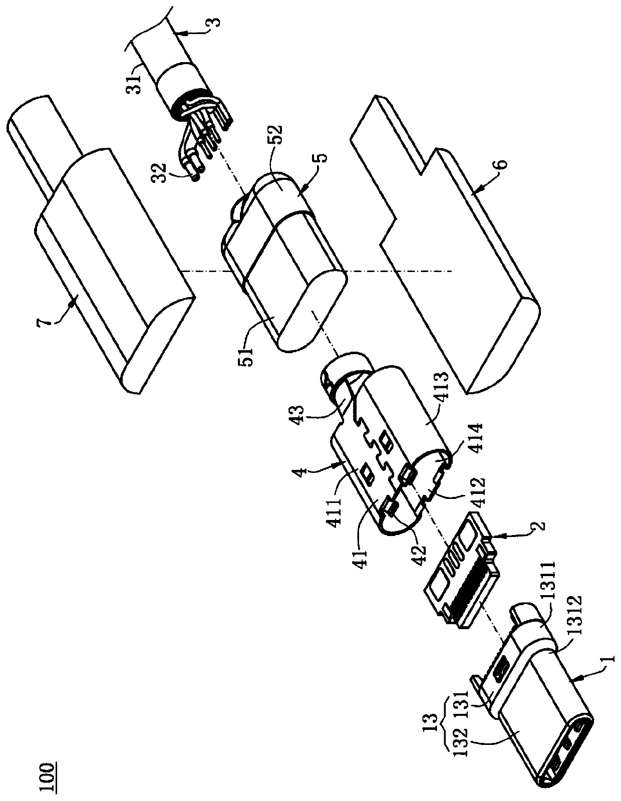
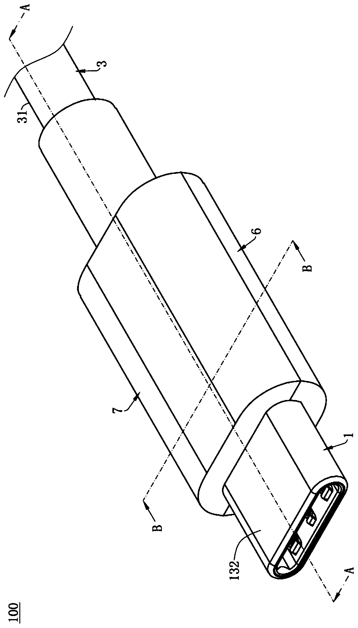
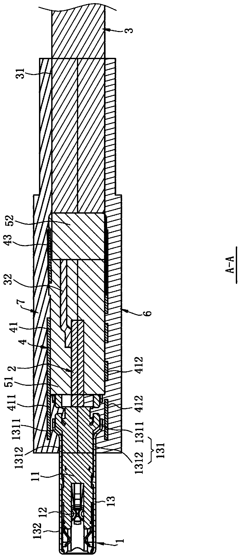
[0037] Please refer to Figure 1 to Figure 7 , is the main embodiment of a manufacturing method of a new cable connector assembly 100 of the present invention, and the cable connector assembly 100 includes a plug connector 1, a circuit board 2, a cable 3, and a housing 4 , an inner mold 5, a first outer mold 6, a second outer mold 7.

[0038] Please refer to figure 1 , Image 6, the plug connector 1 is a connector conforming to the Type-C standard in this embodiment, and the plug connector 1 includes an insulating body 11, a plurality of terminals 12 accommodated in the insulating body 11, and a shielding sheet (unnumbered) and two metal sheets (unnumbered), a shielding shell 13 surrounding the insulating body 11. The shiel...


PUM


Abstract

The invention discloses a manufacturing method of a cable connector assembly. The manufacturing method is characterized by comprising the following steps: step S1: a plug connector is provided, wherein the plug connector comprises an insulating body, multiple terminals accommodated in the insulating body and a shielding case surrounding the insulating body, and the shielding case is provided witha base and a butting part extending from the base to be inserted into a pair of connectors and electrically connects a cable and the terminals; step S2, a shell covers the base and the cable and fixesthe shell and the shielding case; step S3, injection molding of an inner mold is performed in the shell and the cable is fixed; step S4, the upper surface of the shell is located and injection molding of a first outer mold is performed to cover the lower surface of the shell and the lower surface of the inner mold; and step S5: the lower surface of the first outer mold is located and injection molding of a second outer mold is performed to cover the upper surface of the shell and the upper surface of the first outer mold so that the second outer mold and the first outer mold are joined and the structure of the first outer mold and the second outer mold is uniform.

Description

[0001] 【Technical field】 [0002] The invention relates to a manufacturing method of a cable connector assembly, in particular to a manufacturing method of a high-speed transmission cable connector assembly. [0003] 【Background technique】 [0004] The conventional manufacturing method of the cable connector assembly provides a male head, electrically connects the male head to the cable, sets a metal shell on the periphery of the male head, forms a first insulating member in the metal shell to fix the cable, and then The outer periphery of the first insulator is one-time injection molded to form the second insulator to cover the male head, the first insulator, the metal shell and the cable. However, since the second insulator has to cover multiple components such as the male head, the first insulator, the metal shell, and the cable, the volume of the second insulator must be very large, and the pressure during plastic injection is prone to occur during the injection molding pro...

Claims


Application Information

Patent Timeline
Patent Type & Authority Applications(China)
IPC IPC(8): H01R43/20H01R43/16
CPCH01R43/16H01R43/20
Inventor 钱建成张国威陈祥明段秉琼
Owner DEYI PRECISION ELECTRONIC IND CO LTD PANYU
Why Eureka
Try Eureka