Interspinous process implants having deployable engagement arms

a technology of interspinous process and engagement arms, which is applied in the field of spinal implants, can solve the problems of spinal canal narrowing and compression of spinal cord or nerve roots, pain and numbness in the back and legs, weakness and/or loss of balance,

Active Publication Date: 2012-03-27
SPINAL SIMPLICITY
View PDF142 Cites 60 Cited by
  • Summary
  • Abstract
  • Description
  • Claims
  • Application Information

AI Technical Summary

Benefits of technology

[0012]A drive assembly can be provided, extending into the interior cavity of the threaded body portion for selectively moving the engagement members in tandem from the stowed position to the deployed position. Means for selectively locking the engagement members in the deployed position, operatively associated with the drive assembly, can be provided. The drive assembly can include a main drive shaft that extends into the interior cavity of the body portion along the longitudinal axis of the body portion. The drive shaft can include a transmission end having a plurality of beveled gear teeth for operatively meshing with the beveled gear teeth on the central hubs of each engagement member to facilitate the transmission of torque therebetween.

Problems solved by technology

Over time, the ligaments and bone that surround the spinal canal can thicken and harden, resulting in a narrowing of the spinal canal and compression of the spinal cord or nerve roots.
This condition is called spinal stenosis, which results in pain and numbness in the back and legs, weakness and / or a loss of balance.
While some patients may experience relief from symptoms of spinal stenosis with such treatments, many do not, and thus turn to surgical treatment.
However, implantation of the X-STOP® device still requires an incision to access the spinal column to deploy the X-STOP® device.

Method used


Image

  • Interspinous process implants having deployable engagement arms
  • Interspinous process implants having deployable engagement arms
  • Interspinous process implants having deployable engagement arms

Examples


Embodiment Construction

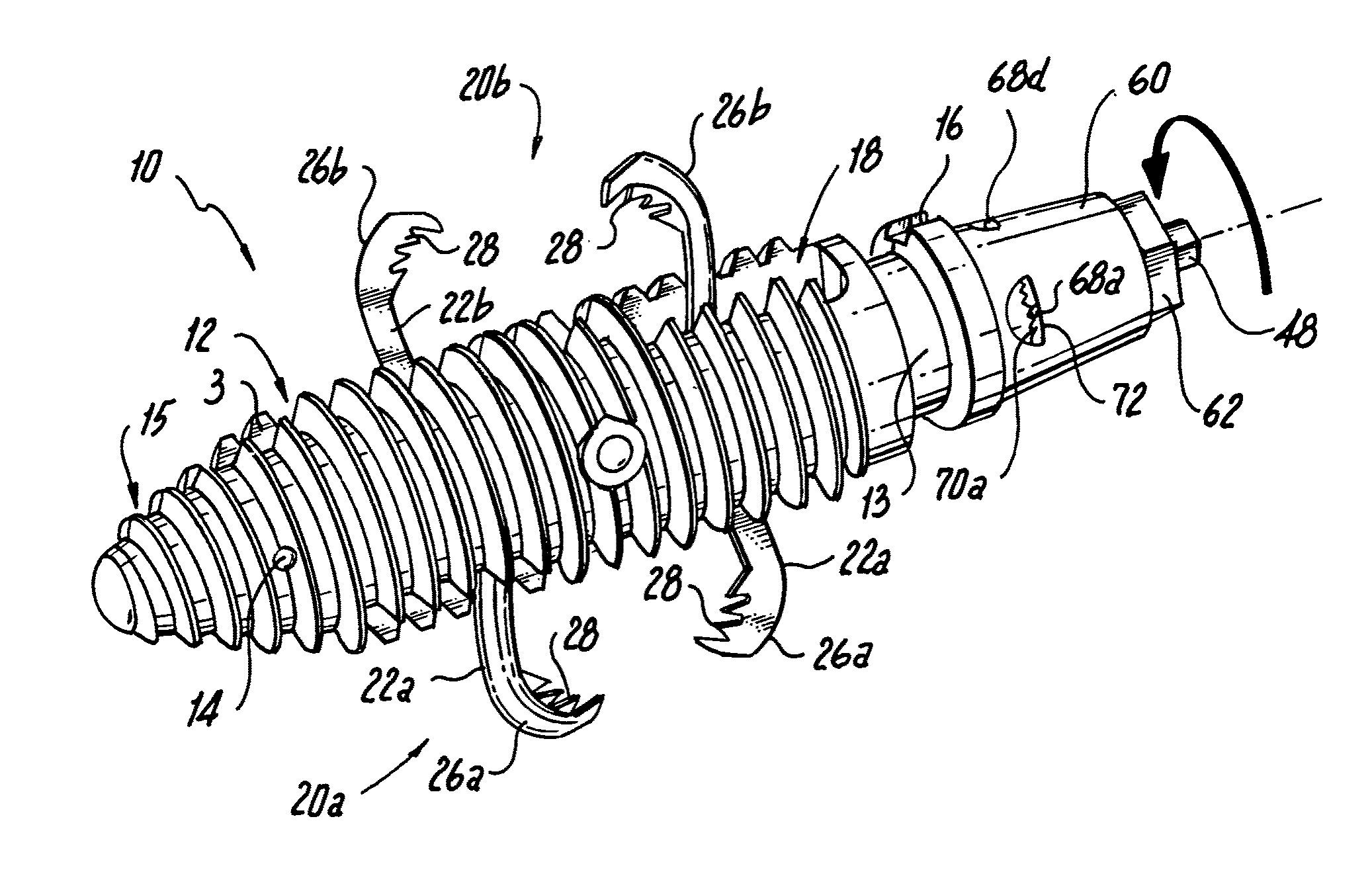
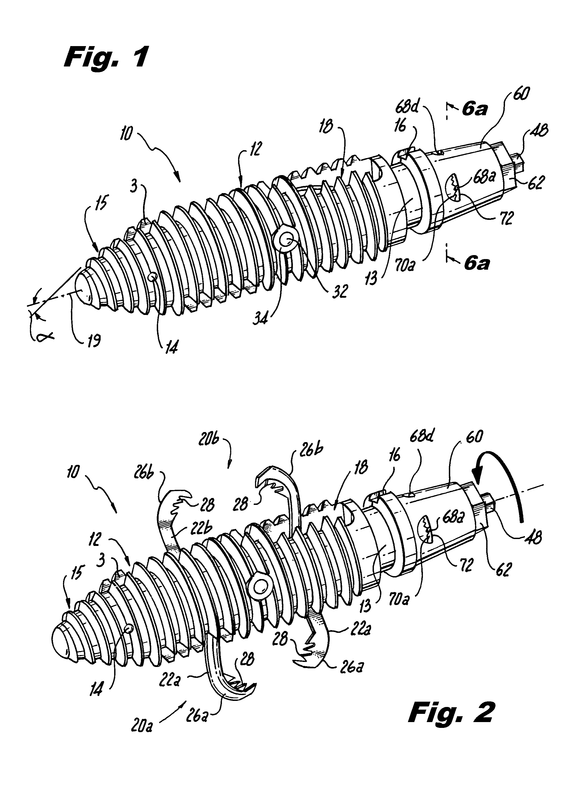
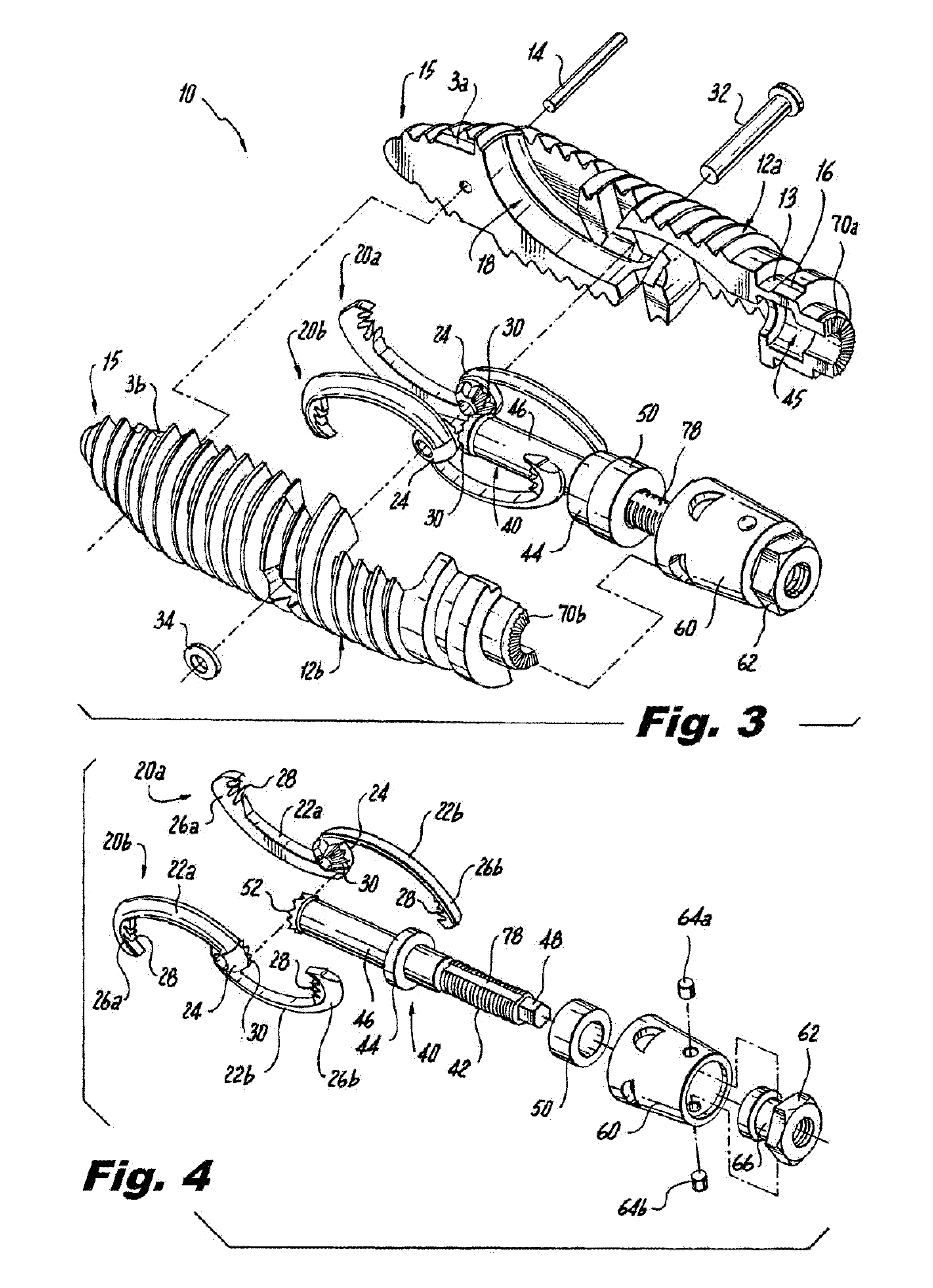
[0049]Referring now FIG. 1, there is illustrated one exemplary embodiment of an interspinous implant constructed in accordance with a preferred embodiment of the subject invention and designated generally by reference numeral 10. Implant 10 is particularly well adapted for use in performing minimally invasive surgical procedures for treating spinal stenosis, including, for example, interspinous process decompression (IPD).

[0050]It is envisioned however, that the implant 10 of the subject invention can be used in other spinal procedures as well, including, but not limited to as an adjunct to spinal fusion procedures, or as a spinal stabilization device. Those skilled in the art will readily appreciate from the following description that the interspinous process implant of the subject invention is well adapted for percutaneous insertion, and thus overcomes many of the deficiencies of prior art devices presently used in IPD procedures. That is, the implant 10 is dimensioned and configu...


PUM


Abstract

Spinal implants include an elongated body portion dimensioned and configured for percutaneous introduction into a target interspinous process space, at which interspinous distraction and / or spinal fusion are desired. The body portion can include a threaded outer surface, or alternatively a smooth surface. The body portion can include one or more interior cavities, and can include deployable engagement members adapted and configured to move in tandem between a stowed position retracted within the interior cavity of the body portion and a deployed position extended from the interior cavity of the body for engaging adjacent spinous processes. An internal drive assembly for selectively moving the engagement members from the stowed position to the deployed position can be provided, as can a elements for locking the engagement members in a deployed position.

Description

CROSS-REFERENCE TO RELATED APPLICATIONS[0001]This application is a continuation-in-part application of, and claims the benefit of priority to U.S. patent application Ser. No. 12 / 011,905, filed Jan. 30, 2008, which in-turn claims priority to U.S. Patent Application Ser. No. 61 / 001,430, filed Nov. 1, 2007, U.S. Patent Application Ser. No. 61 / 000,831, filed Oct. 29, 2007, U.S. Patent Application Ser. No. 60 / 961,780, filed Jul. 24, 2007, U.S. Patent Application Ser. No. 60 / 959,799, filed Jul. 16, 2007, and U.S. Patent Application Ser. No. 61 / 007,916, filed May 1, 2007. This application also claims the benefit of priority to U.S. Patent Application Ser. No. 61 / 207,339, filed Feb. 11, 2009. Each of the aforementioned patent applications is incorporated herein by reference in its entirety.BACKGROUND OF THE INVENTION[0002]1. Field of the Invention[0003]The subject invention is directed to spinal implants, and more particularly, to an interspinous process implant with a threaded body and dep...

Claims


Application Information

Patent Timeline
Patent Type & Authority Patents(United States)
IPC IPC(8): A61B17/70
CPCA61B17/7065A61B2017/0256
Inventor HESS, HAROLD
Owner SPINAL SIMPLICITY
Why Eureka
Try Eureka