
System and a method for altering the geometry of the heart

a technology of geometry and heart, applied in the field of system and a method for altering the geometry of the heart, can solve the problems of fundamental cause of morbidity and mortality, valve becomes insufficient, and the mitral regurgitation is the main cause of death, so as to achieve an advanced approach

Active Publication Date: 2012-03-27
EDWARDS LIFESCIENCES AG
View PDF232 Cites 256 Cited by
  • Summary
  • Abstract
  • Description
  • Claims
  • Application Information

AI Technical Summary

Benefits of technology

Enables precise adjustment and stabilization of the heart's geometry on a beating heart, improving valve competence and reducing further dilatation of left heart chambers, thus addressing the limitations of existing treatments.

Problems solved by technology

Despite advances in pharmacologic and interventional therapy, development of functional ischemic mitral regurgitation (MR) after myocardial infarction remains a fundamental cause of morbidity and mortality, especially in western societies.
Displacement of these cardiac muscular prominences hamper correct closure of the mitral valve during the ventricular systole and therefore the valve becomes insufficient.
However, these principles of treatment are fairly primitive or crude, and therefore do not match the complex anatomy, physiology and mechanics related to the functionality of the mitral valve.
The adjustment of the functional constituents of the devices—the tension members—during heart arrest may therefore be inaccurate, and the geometry of the device and the heart cannot be altered once the heart is surgically closed, and cardiac function is resumed after the insertion of the device.
Therefore, it is difficult to asses if the desired geometry is restored at this stage—before the heart function is resumed.
Since the heart with its valves and subvalvular apparatus is a complex dynamic system, where the individual components move in an interdependent and coordinated manner, such an assessment may be extremely difficult.

Method used


Image

  • System and a method for altering the geometry of the heart
  • System and a method for altering the geometry of the heart
  • System and a method for altering the geometry of the heart

Examples


Embodiment Construction

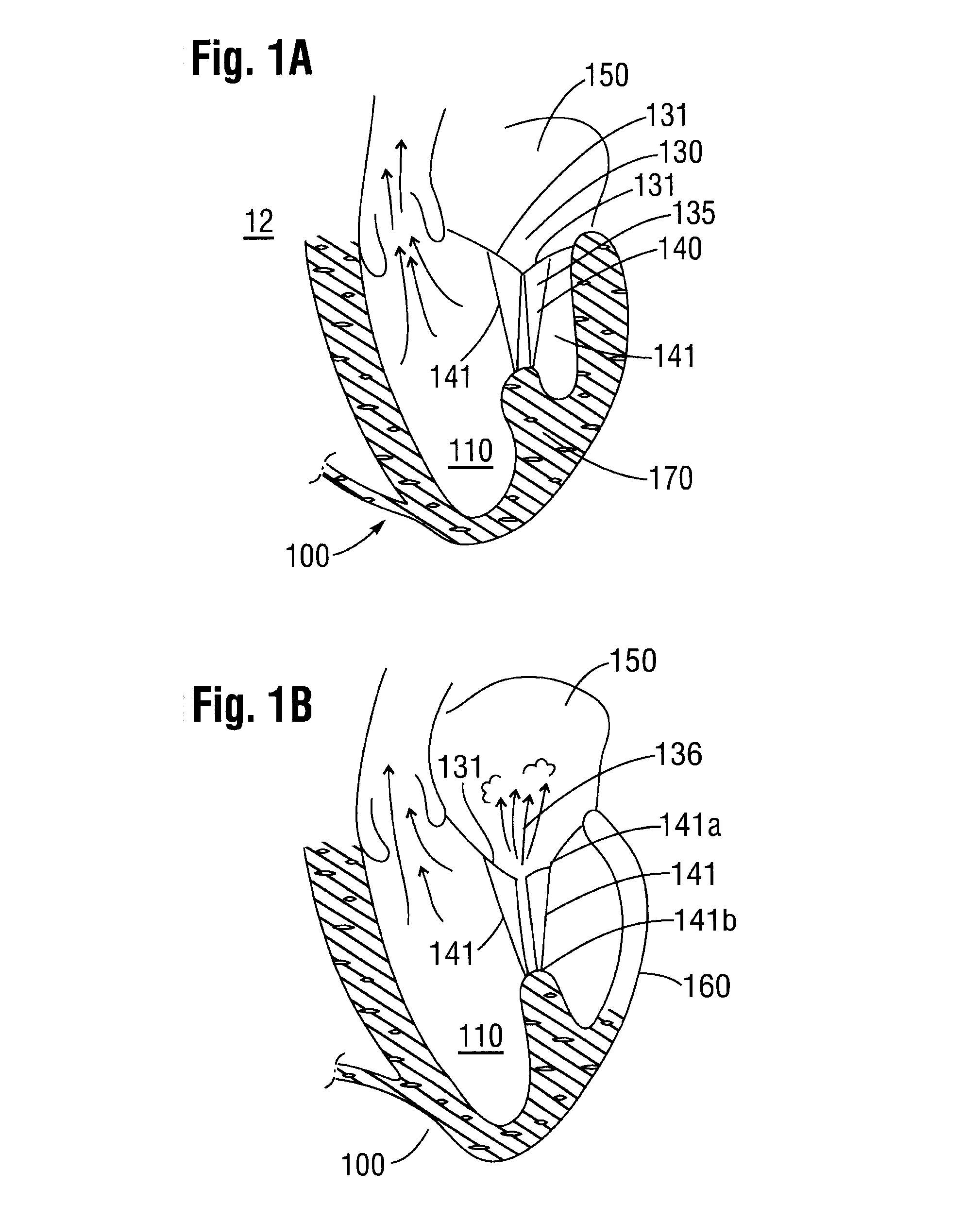
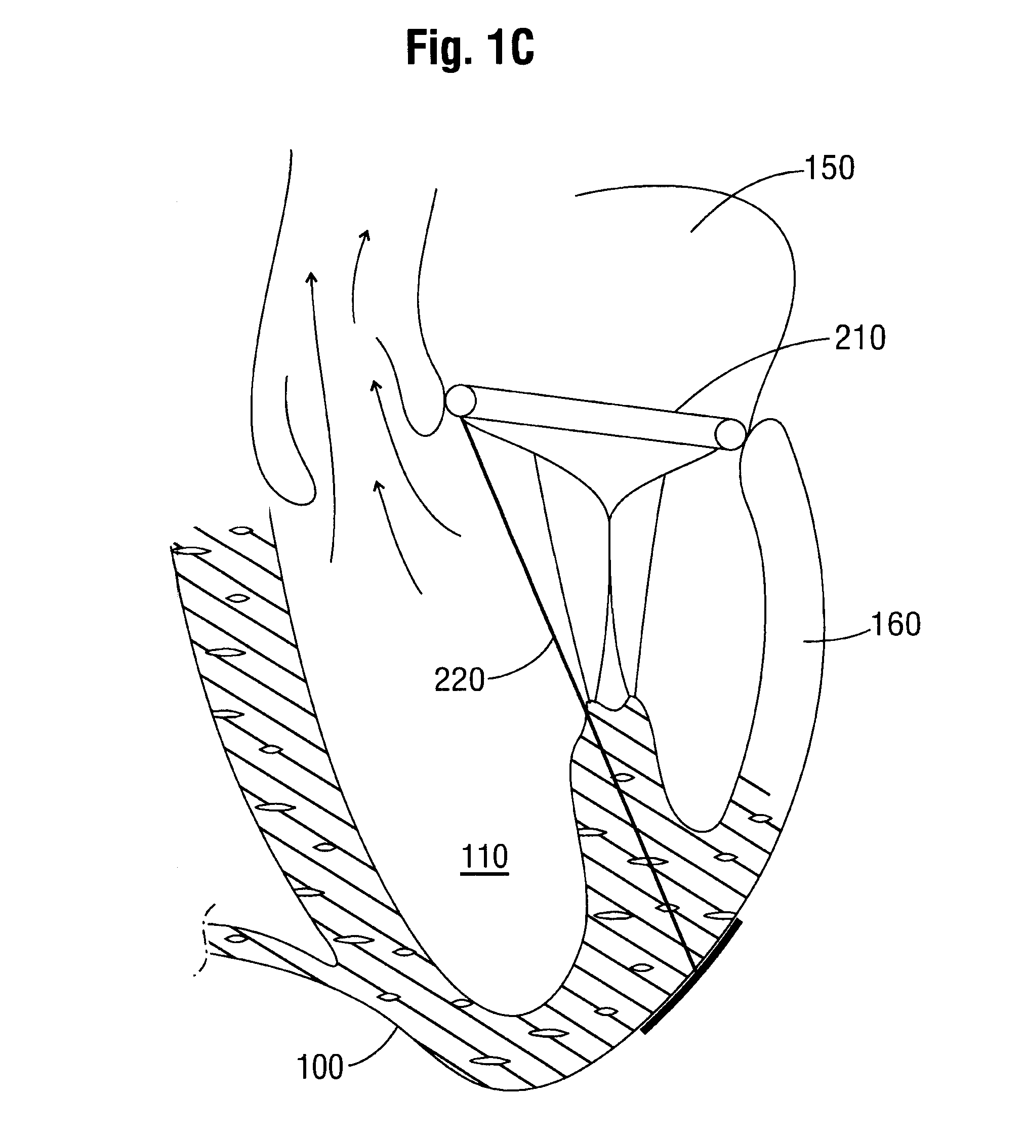
[0046]Initially and in order to describe the present invention, an example of a physical condition of a heart 100 that can be remedied using the system and the method of the present invention is briefly described with reference to FIGS. 1A-C. FIG. 1A shows a section through a portion of a normally functioning heart 100. More particularly, FIG. 1A shows in schematic form a long-axis section through a left ventricle 110 of a normal heart 100 during systole. The aortic valve 120 is open (the arrows in the vicinity of the valve 120 indicating the flow of blood), while the mitral valve 130 is closed. The mitral valve 130 has two leaflets 131. Primary and secondary chordae 140, 141 ensures that the two leaflets 131 of the mitral valve 130 interact over a broad, so-called coaption area 135 to ensure a tight mitral valve 130 function, thus preventing blood to re-enter the left atrium 150 (mitral regurgitation 136, see FIG. 1B). In the figure (FIG. 1A) also one papillary muscle 170 is shown....


PUM


Abstract

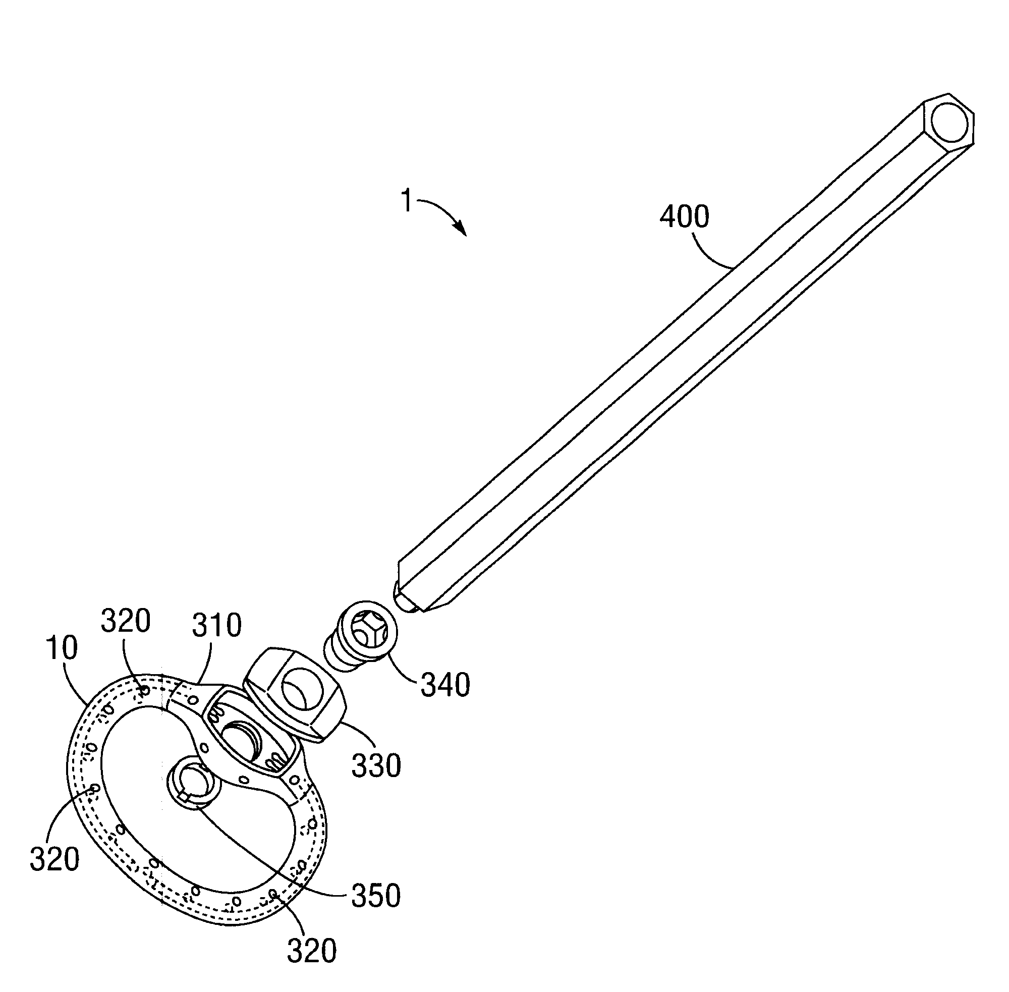
A system (1) for altering the geometry of a heart (100), comprising an annuloplasty ring; a set of elongate annulus-papillary tension members (21, 22, 23, 24), each of which tension members are adapted for forming a link between said ring (10) and a papillary muscle, each of said tension members (21, 22, 23, 24) having a first end (21b, 22b, 23b, 24b) and a second end (21a, 22a, 23a, 24a); and a first set of papillary anchors (30) for connecting each of the first ends (21b, 22b, 23b, 24b) of said tension members (21, 22, 23, 24) to said muscle; and where said annuloplasty ring (10) has at least one aperture (12, 13); where each of said annulus-papillary tension members (21, 22, 23, 24) are extendable through said ring (10) through said apertures (11, 12, 13), and through an atrium to an exterior side of said atrium, such that the distance of each link between the annulus and the muscles is adjustable from a position exterior to the heart.

Description

CROSS REFERENCE TO RELATED APPLICATION[0001]This application claims the benefit and priority to and is a U.S. National Phase of PCT International Application Number PCT / DK2007 / 050058, filed on May 15, 2007, designating the United States of America and published in the English language, which is an International Application of and claims the benefit of priority to Danish Patent Application No. PA 2006 00684, filed on May 15, 2006, and U.S. Provisional Application No. 60 / 809,383, filed on May 31, 2006. The disclosures of the above-referenced applications are hereby expressly incorporated by reference in their entireties.[0002]The present invention concerns a system for altering the geometry of a heart. The invention further concerns a method for altering the geometry of a heart. More specifically the invention concerns a system comprising a number of tension members adapted for restoring the internal geometry of ischemically or otherwise damaged heart chambers. The system can furtherm...

Claims


Application Information

Patent Timeline
Patent Type & Authority Patents(United States)
IPC IPC(8): A61F2/24
CPCA61B17/0401A61B17/0467A61F2/2466A61F2/2445A61F2/2454A61B2017/00238A61B2017/00243A61F2/2457A61B2017/0417
Inventor HASENKAM, JOHN MICHAELSMERUP, MORTENNIELSEN, STEN LYAGER
Owner EDWARDS LIFESCIENCES AG
Learn More