Regulating device for regulating the voltage on a high-side load

Active Publication Date: 2012-03-27
SITRONIC GES FUER ELEKTROTECHNISCHE AUSRUSTUNG MBH & CO KG
View PDF13 Cites 0 Cited by
  • Summary
  • Abstract
  • Description
  • Claims
  • Application Information

AI Technical Summary

Benefits of technology

[0013]The invention enables a control system, in particular for a fan, to be constructed with comparatively few discrete components. The control system is distinguished by a good control response and an extremely small quiescent current consumption.

Problems solved by technology

If, for reasons of cost, it is desired to dispense with an encapsulation of the regulator electronics, then the use of high-impedance resistors is problematic.
Condensation and the contaminations associated therewith on the circuit board surface that occur in the vehicle lead to leakage currents, which affect the function of switching circuits designed with high impedance.

Method used


Image

  • Regulating device for regulating the voltage on a high-side load
  • Regulating device for regulating the voltage on a high-side load
  • Regulating device for regulating the voltage on a high-side load

Examples


Embodiment Construction

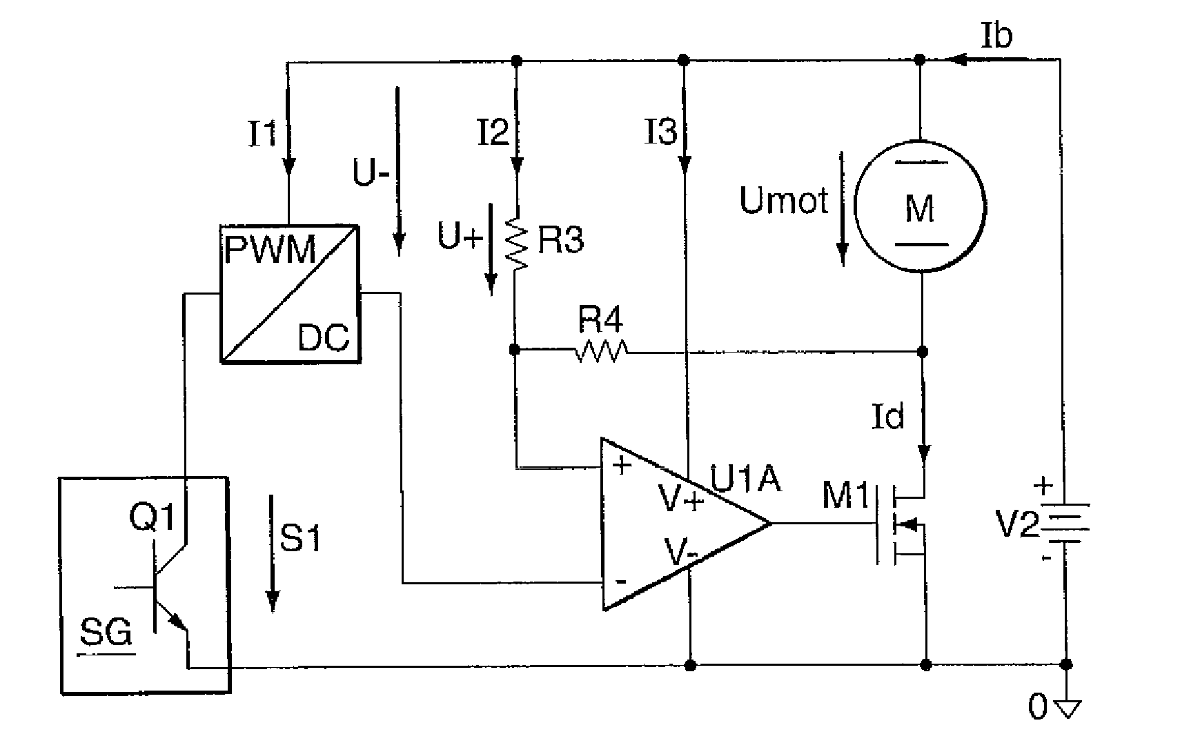
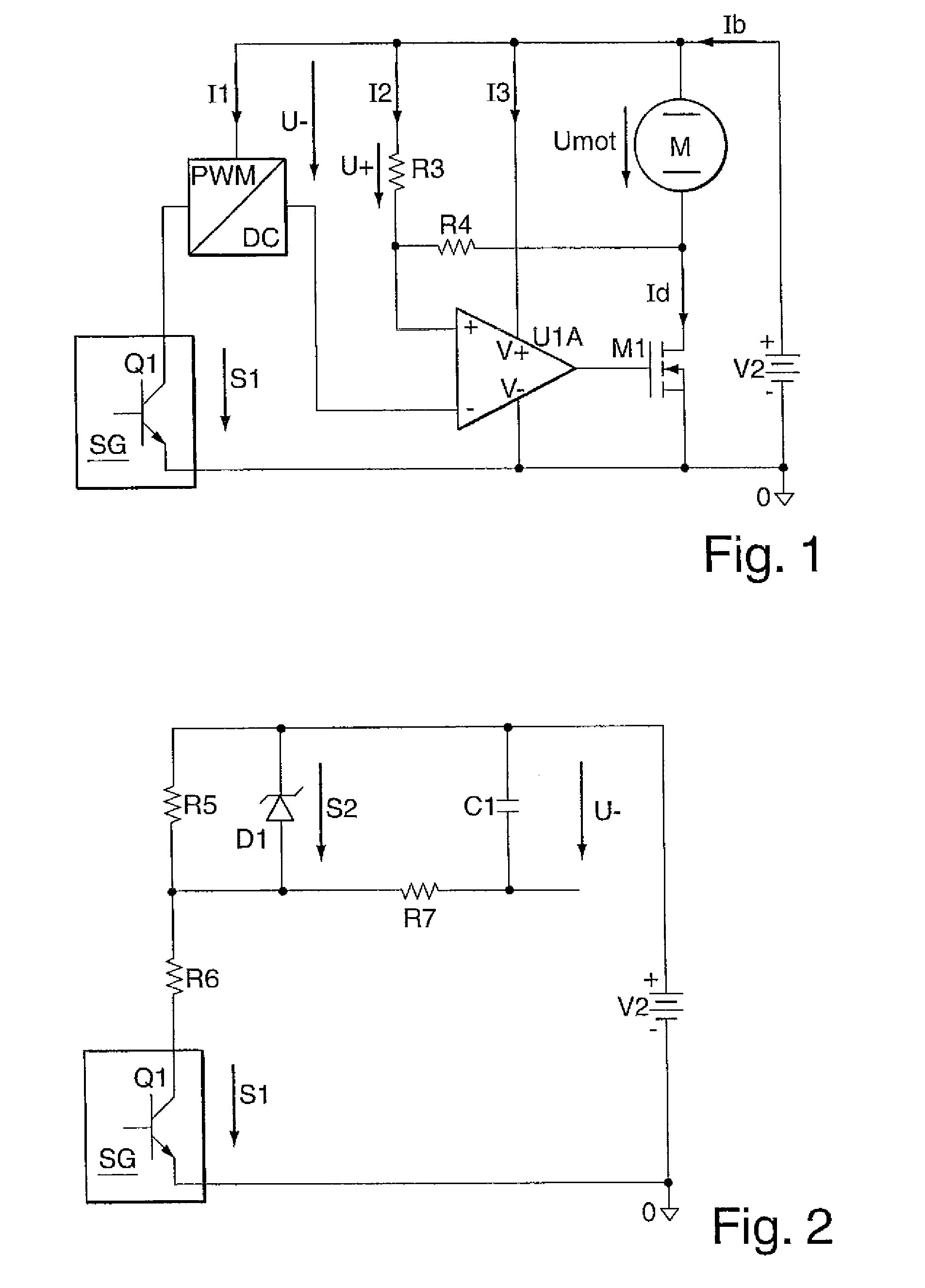
[0018]According to FIG. 1, the pulse width-modulated control signal S1 of a control unit SG of an air-conditioning system is used to generate a control voltage U−, which relates firstly to the positive supply voltage V2 and the magnitude of which is clearly functionally linked to the duty factor of the control signal S1.

[0019]In the preferred embodiment, the pulse width-modulated control signal S1 is related to earth.

[0020]The two input voltages of the regulator U1A are related to the positive supply voltage V2. So according to the circuit diagram of FIG. 1, Umot is

[0021]Umot=U-·(1+R4R3)

and so independent of V2.

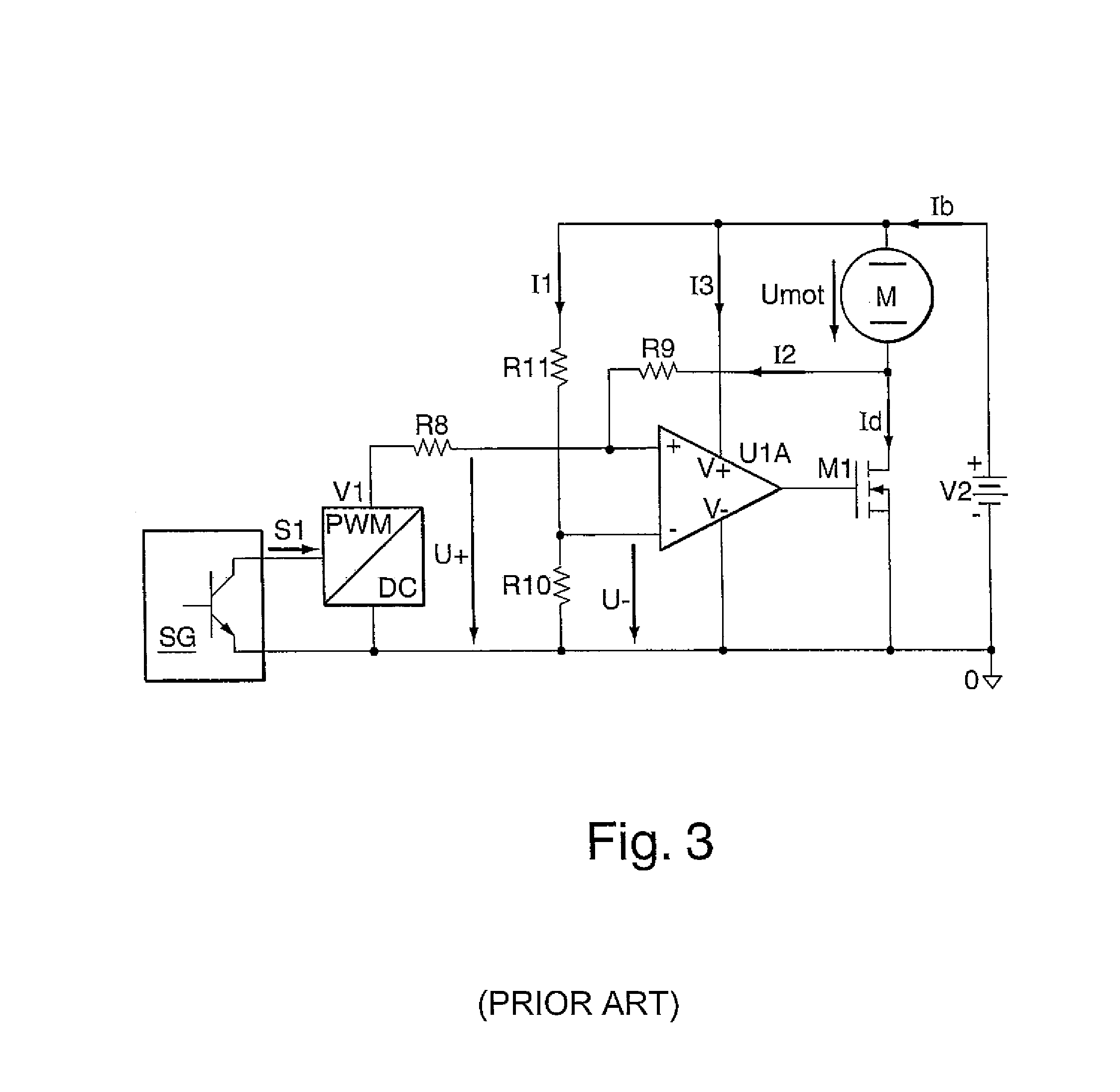
[0022]In contrast to FIG. 1, resistance tolerance pairings are not taken into account in the relation dUmot=f(dV2).

[0023]According to the teaching of the invention, on-board voltage fluctuations are therefore smoothed out in an improved manner.

[0024]The regulator U1A recognises when the output signal of the PWM / DC inverter, i.e. U, falls below a specific threshold value and i...


PUM


Abstract

The invention to an electronic control system, controlled by a pulse width-modulated signal (SG) related to earth, for regulating the voltage (Umot) across a high-side load (M), in particular a fan control unit for motor vehicles. The circuit part that converts the pulse width-modulated signal (SG) into the reference input variable (U−) needed for the regulation uses the positive potential of the supply voltage (V2) as reference potential, so that the reference input variable (U−) is likewise related to the positive potential of the supply voltage and the control signal (SG) is converted by means of a Zener diode (D1) and by means of a resistor (R5) connected parallel to the Zener diode (D1) into a control signal related to the positive supply potential and is further converted with a low pass filter (R7, C1) into a linear control signal, which serves as input reference variable (U−).

Description

[0001]The invention relates to an electronic regulating system, controlled by a pulse width-modulated signal, for regulating the voltage across a high-side load, in particular a fan regulator for motor vehicles.[0002]Such regulating systems are generally well known through their use in motor vehicles.[0003]Japanese Patent JP 01302409 AA discloses an electronic regulating system for regulating the voltage, having a reference input variable related to the positive potential of the supply voltage for the regulation.[0004]Japanese Patent JP 09215321 AA discloses a regulating system having a circuit part that converts the pulse width-modulated signal into the reference input variable needed for the regulation. The earth is used here as a reference potential.[0005]An important basic function of the regulating system is the regulation of the motor voltage as a function of a control signal. This control signal may be an analogue control voltage, an analogue control current or a digital sign...

Claims


Application Information

Patent Timeline
IPC IPC(8): H02P7/00
CPCH02M3/156
Inventor ZAMETZKY, KLAUS
Owner SITRONIC GES FUER ELEKTROTECHNISCHE AUSRUSTUNG MBH & CO KG
Why Eureka
Try Eureka