Device for placing sleeves on traveling articles

a technology for traveling articles and sleeves, applied in the field of sleeves, can solve the problems of complicated organization of sleeves-placing devices, limited rates, and often poorly placed sleeves on articles

Active Publication Date: 2012-04-03
SLEEVER INT
View PDF21 Cites 15 Cited by
  • Summary
  • Abstract
  • Description
  • Claims
  • Application Information

AI Technical Summary

Benefits of technology

[0019]Thus, the above-specified characteristics make it possible to guarantee that the free end of the sheath is always properly pinched by the second wheels for ejection of the cut-off segments prior to being held stationary for the cutting and ejection pass. Such an advance beyond the point of tangential contact guarantees that the sheath is stopped with positive engagement, thereby de facto eliminating any risk of the sheath sliding on the shaper, and thus contributing to obtaining a completely regular cut edge. It is easy to understand that the process of ejecting the cut-off sheath segment can start instantly, without any dead time, because of the above-mentioned positive engagement.

Problems solved by technology

Nevertheless, it has been found that the above-mentioned techniques impose limits in terms of rates of throughput, since when high rates are reached, it is found that the sheaths are frequently poorly positioned on the articles, particularly when they constitute sleeves of considerable height.
The two above-mentioned requirements thus considerably complicate organizing sleeve-placing devices, and mention can be made of one type of technical problem that is becoming more and more awkward, and this relates to positioning the sheath on the shaper at the time it is being held stationary for the cutting and ejection pass.
Nevertheless, it has been found that by causing such a device to operate at very high rates of throughput, the above-mentioned bell-shaped curves give rise to problems in terms of accuracy at the end of the advance / eject cycle, even when adopting a virtual-shaft common electronic programmer.
This lack of accuracy is also to be found when the sleeve-placing device is stopped, prior to a new period of operation, such that the position of the sheath is de facto inaccurate when operation restarts.
A direct consequence of this is that the axial position of the sheath on the shaper is never defined with complete accuracy.
The height of the segment is never accurately constant and it is never possible to completely eliminate the risk of the sheath slipping on the shaper at the time it is being held stationary for the cutting and ejection pass.

Method used


Image

  • Device for placing sleeves on traveling articles
  • Device for placing sleeves on traveling articles
  • Device for placing sleeves on traveling articles

Examples


Embodiment Construction

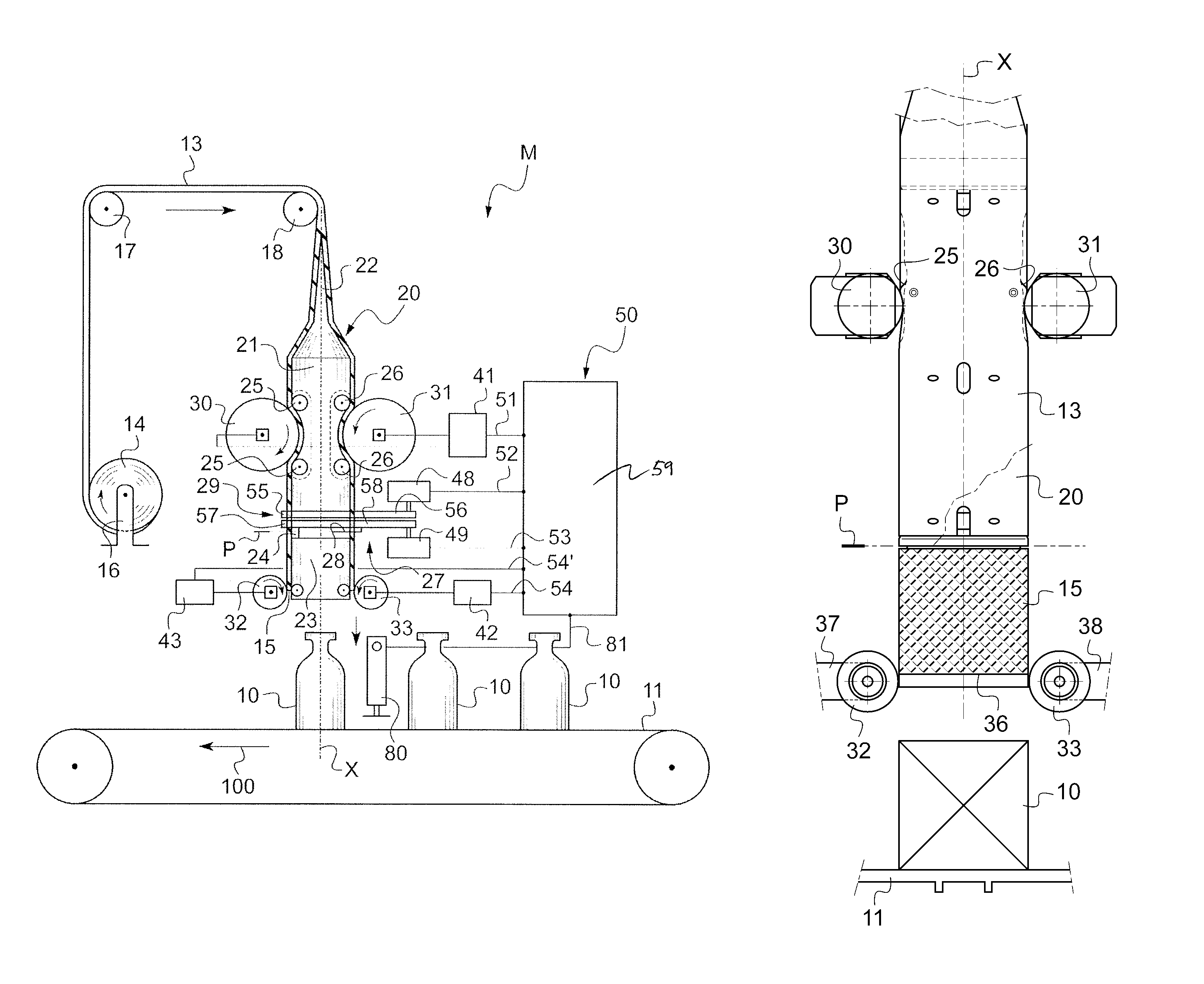
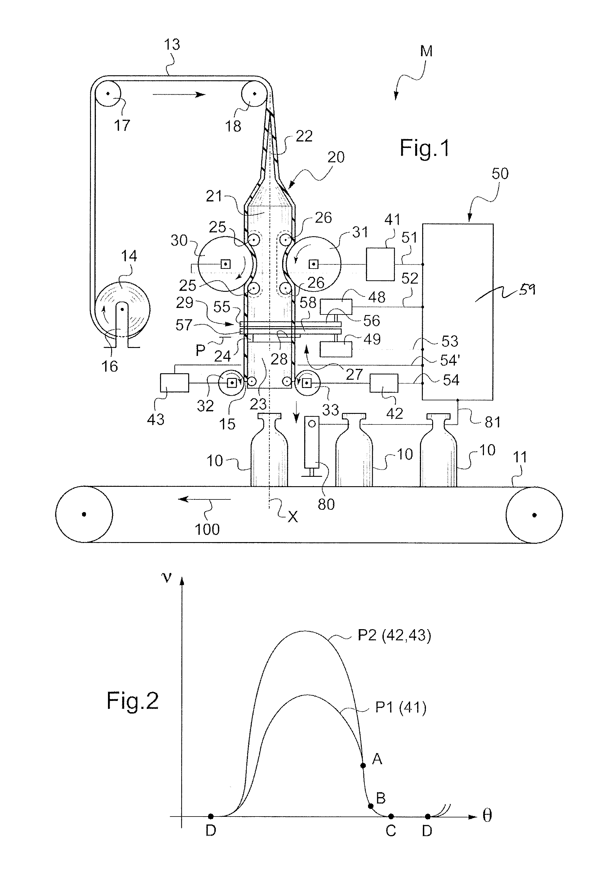
[0033]In FIG. 1, there can be seen a sleeve-placing machine referenced M, serving to place sleeves on traveling articles, and arranged in accordance with the invention.

[0034]The sleeve-placing machine M has a certain number of points in common with the sleeve-placing machine described in above-mentioned document WO-A-99 / 59871 in the name of the Applicant. These elements in common are therefore described briefly, however reference can be made to the above-mentioned document for more ample details.

[0035]The articles 10, here shown in the form of bottles, are traveling on a conveyor belt 11 in a direction referenced 100, with the travel of the conveyor belt being driven by associated means that are not shown.

[0036]A flat sheath of heat-shrink plastics material 13 is delivered from a reel 14 mounted to rotate on a portion of a structure 16, said sheath passing over two deflector rollers 17 and 18 to be brought over a shaper 20 for opening the sheath. The sheath-opening shaper 20, here h...


PUM

PropertyMeasurementUnit
distanceaaaaaaaaaa
thicknessaaaaaaaaaa
thicknessaaaaaaaaaa

Abstract

The invention relates to a device for placing sleeves on traveling articles, said sleeves being cut from a continuous sheath passing over a sheath-opening shaper, first outer wheels serving to advance the sheath along the shaper, and second outer wheels being provided downstream from cutter means for the purpose of ejecting the cut-off sheath segment, said wheels being driven in rotation by associated electric motors controlled synchronously by a virtual-shaft common electronic programmer. In accordance with the invention, the programmer is arranged to determine a continuous profile of speed variation for the associated electric motors, said profiles being bell-shaped and having a common end segment in which the profiles coincide, this corresponding to the motors having identical speeds, the length of the common end segment being selected so that the sheath is advanced beyond the point of tangential contact with the second wheels so that said sheath is pinched by said second wheels prior to being held stationary for the cutting and ejection pass.

Description

CROSS REFERENCE TO RELATED APPLICATION[0001]Applicant hereby claims foreign priority benefits under U.S.C. §119 from French Patent Application No. 08 04599 filed on Aug. 14, 2008, the contents of which are incorporated by reference herein.FIELD OF THE INVENTION[0002]The present invention relates to placing sleeves, in particular heat-shrink sleeves, on traveling articles, the sleeve-covered articles then passing through a shrinking oven.BACKGROUND OF THE INVENTION[0003]To place heat-shrink sleeves on traveling articles, it is conventional to use a technique whereby the sleeves are cut from a continuous sheath that passes over a sheath-opening shaper, which shaper is held floating by co-operation between outer wheels and backing wheels of parallel axes carried by the shaper, which outer wheels serve to cause the sheath to advance along the shaper (which is generally vertical) up to and beyond cutter means. Other wheels are generally provided downstream from the cutter means to eject ...

Claims


Application Information

Patent Timeline
Patent Type & Authority Patents(United States)
IPC IPC(8): B65B11/02
CPCB65B9/14B65B61/06B65C3/065B65B53/02
Inventor FRESNEL, ERIC
Owner SLEEVER INT
Why Eureka
Try Eureka