Accessory sub-cooling unit and method of use

a sub-cooling unit and accessory technology, applied in the field of refrigerant based heat exchange systems, can solve the problems of ineffectiveness, high cost and complexity, and inability to meet the needs of customers, and achieve the effect of improving the efficiency of a refrigerated air conditioning system and being easy to install

Active Publication Date: 2012-04-03
SNOW III AMOS A
View PDF28 Cites 2 Cited by
  • Summary
  • Abstract
  • Description
  • Claims
  • Application Information

AI Technical Summary

Benefits of technology

[0017]The present invention overcomes many of the disadvantages of the prior art by providing a simplified, yet effective system and method for improving the efficiency of a refrigerated air conditioning system utilizing a vapor-compression refrigeration cycle. The improved system includes an accessory sub-cooling unit which is fluidly connected between the condensing coil and the expansion valve in a closed loop refrigeration system utilizing a vapor-compression refrigeration cycle. The accessory sub-cooling unit comprises a serpentine heat exchange tube having one end fluidly connected downstream of the condensing coil prior to the expansion valve. The accessory sub-cooling unit further comprises a plurality of parallel planar heat transfer fins to assist the heat transfer from the heat exchange tube to the ambient air. In accordance with the method of the present invention, the accessory sub-cooling unit is mounted to a side of the condenser unit in order to utilize the existing air flow generated by the exhaust fan of the condenser unit. Novel features of the invention include that it is an independent cooling system used only to subcool the temperature of liquid refrigerant exiting the condensing coil and that it utilizes the existing air flow generated by the exhaust fan of the condenser unit. Moreover, the accessory sub-cooling unit of the present invention is inexpensive, easy to install.

Problems solved by technology

However, both of these solutions are not economically efficient in view of present costs of materials and energy.
This art typically comprises expensive and complicated counterflow heat exchanger type add-on or retrofit for existing refrigeration systems or the like.
While these units have been around for years, it is generally accepted that they have not been successful because the increase in efficiency of the subcooling unit working alone does not justify the cost of the unit.

Method used


Image

  • Accessory sub-cooling unit and method of use
  • Accessory sub-cooling unit and method of use
  • Accessory sub-cooling unit and method of use

Examples


Embodiment Construction

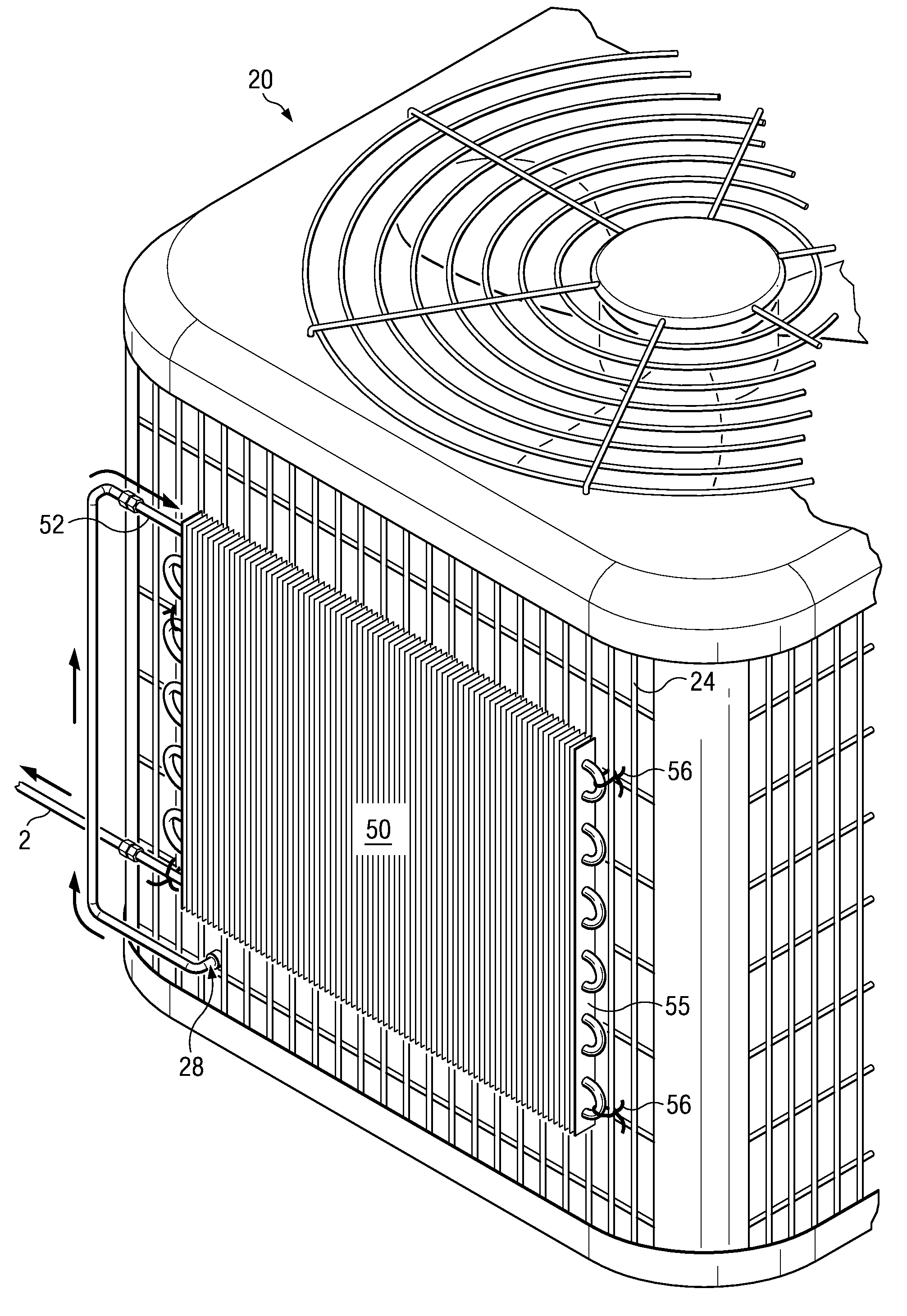
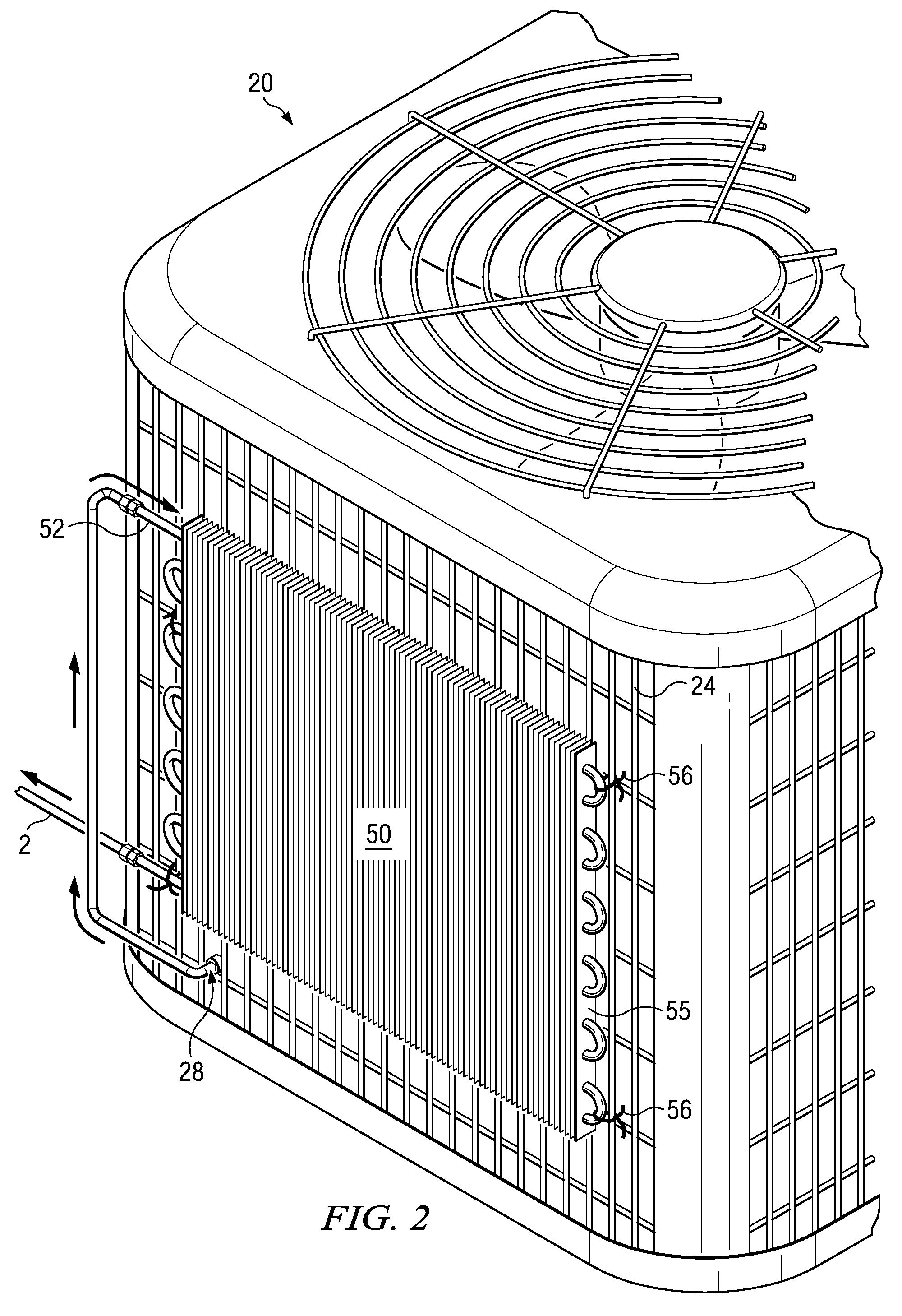
[0025]With reference to FIGS. 2, 3a and 3b, an embodiment of the accessory sub-cooling unit 50 of the present invention is shown. The unit 50 is mounted to the exterior of the condenser unit 20 of a vapor-compression refrigeration system. The accessory sub-cooling unit 50 comprises a serpentine heat exchange tube 52 fluidly connected downstream of the condensing unit 20 in a closed loop refrigeration system utilizing a vapor-compression refrigeration cycle. The heat exchange tube 52 includes an inlet 51 and an outlet 59. The inlet 51 is fluidly connected to the outlet 28 of the condensing coil 22 of the condenser unit 20. The outlet 59 of heat exchange tube 52 is fluidly connected to the conduit 2, which is, in turn, fluidly connected to the throttling or expansion valve located in the air handler 12 of a vapor-compression refrigeration cycle.

[0026]In a preferred embodiment, the heat exchange tube 52 comprises a plurality of parallel spaced refrigerant tubes 52a, 52b, 52c, etc. conn...


PUM


Abstract

A system and method for improving the efficiency of a refrigerated air conditioning system utilizing a vapor-compression refrigeration cycle. The improved system includes an accessory sub-cooling unit which is fluidly connected between the condensing coil and the expansion valve in a closed loop refrigeration system utilizing a vapor-compression refrigeration cycle. The accessory sub-cooling unit comprises a serpentine heat exchange tube having one end fluidly connected downstream of the condensing coil prior to the expansion valve. The accessory sub-cooling unit further comprises a plurality of parallel planar heat transfer fins to assist the heat transfer from the heat exchange tube to the ambient air. In accordance with the method of the present invention, the accessory sub-cooling unit is mounted to a side of the condenser unit in order to utilize the existing air flow generated by the exhaust fan of the condenser unit.

Description

CROSS-REFERENCE TO RELATED APPLICATION[0001]This application claims the benefit of and priority to a U.S. Provisional Patent Application No. 61 / 068,704 filed Mar. 10, 2008, the technical disclosure of which is hereby incorporated herein by reference.BACKGROUND OF THE INVENTION[0002]1. Technical Field[0003]The present invention relates generally to refrigerant based heat exchange systems, and more particularly vapor compression refrigeration systems employing a compressor, a condenser, an evaporator and associated fluid circuitry used for air conditioning, food storage refrigeration, and similar applications, and to improvements which result from subcooling the refrigerant prior to it reaching the evaporator.[0004]2. Description of the Related Art[0005]The use of refrigerated air conditioning systems in commercial and residential property has become commonplace and ubiquitous. Indeed, particularly in the South and Southwest, it borders on being a necessity for ordinary life. Over the...

Claims


Application Information

Patent Timeline
Patent Type & Authority Patents(United States)
IPC IPC(8): F25B45/00
CPCF24F1/10F24F1/50F25B40/02F28D1/0435F28D1/0477F28F1/32
Inventor SNOW, III, AMOS A.
Owner SNOW III AMOS A
Why Eureka
Try Eureka