
Drilling tool and drilling method

a drilling tool and drilling method technology, applied in the direction of drilling pipes, rotary drilling, borehole/well accessories, etc., can solve the problems of increasing the pressure of the rinsing fluid and the clogging of the bore, so as to reduce the mechanical load applied to the valve, improve the control characteristics, and slow down the opening of the valve

Inactive Publication Date: 2012-04-03
HILTI AG
View PDF8 Cites 5 Cited by
  • Summary
  • Abstract
  • Description
  • Claims
  • Application Information

AI Technical Summary

Benefits of technology

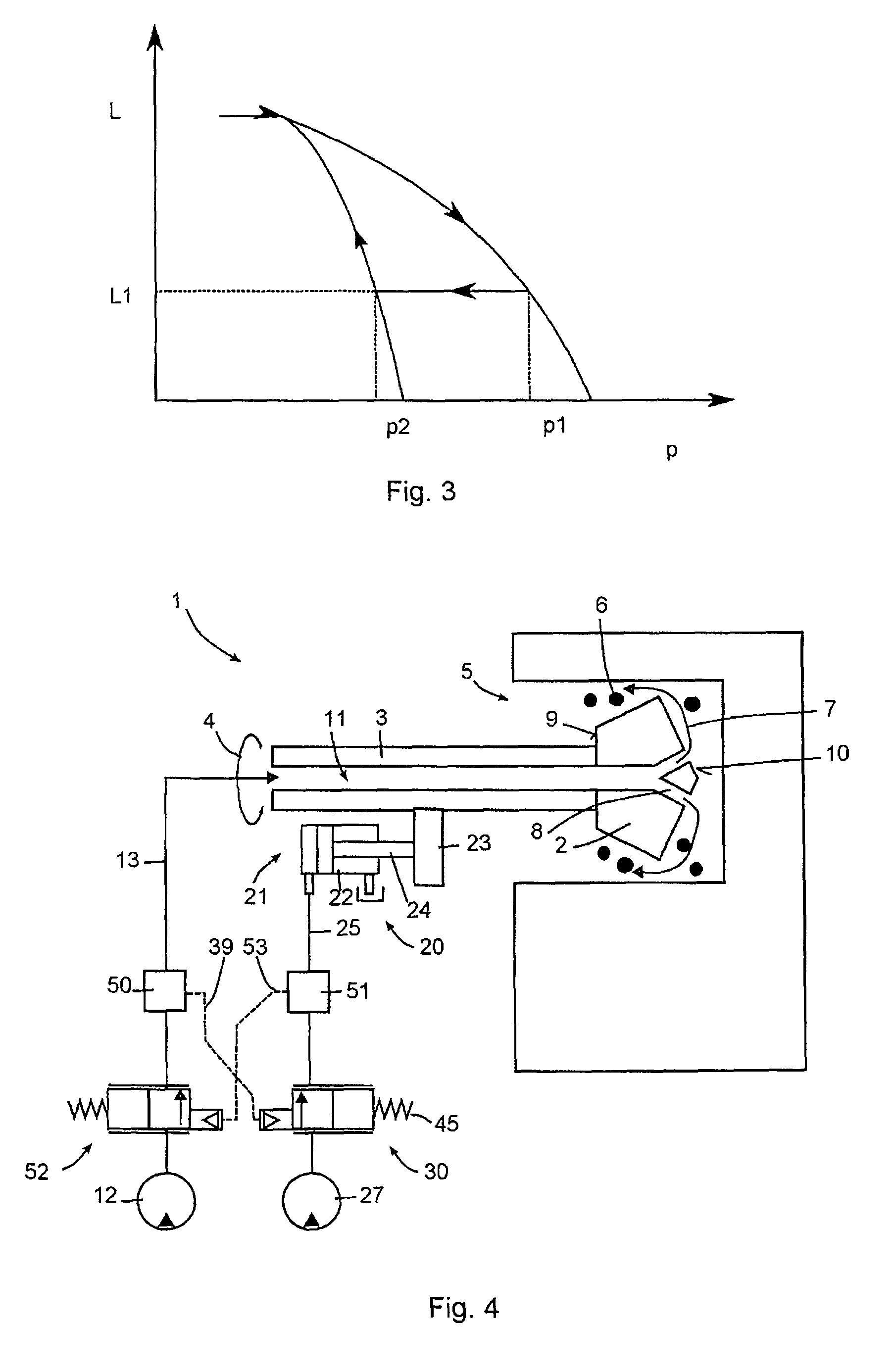
[0011]In the drilling tool, the advancing speed of the drilling head is controlled, dependent on the pressure of the rinsing fluid used for rinsing the bore. The pressure of the rinsing fluid increases when the rinsing fluid is not able to expel the drillings with an adequate delivery rate. As a result, the bore starts to clog. This can happen, e.g., during drilling in a loam layer. In this case, the flow limiter limits the flow of the hydraulic fluid to the advancing device. Preferably, the advancing speed is reduced until the rate of removal of drillings is such that the delivery rate of the rinsing fluid is reduced.
[0014]Electronic components require an electrical supply that need, in part, be additionally made available in mines and open mines. Further, high costs are involved in protection of electrical plug and socket connections and similar contacts against a humid corroding environment and vibrations.
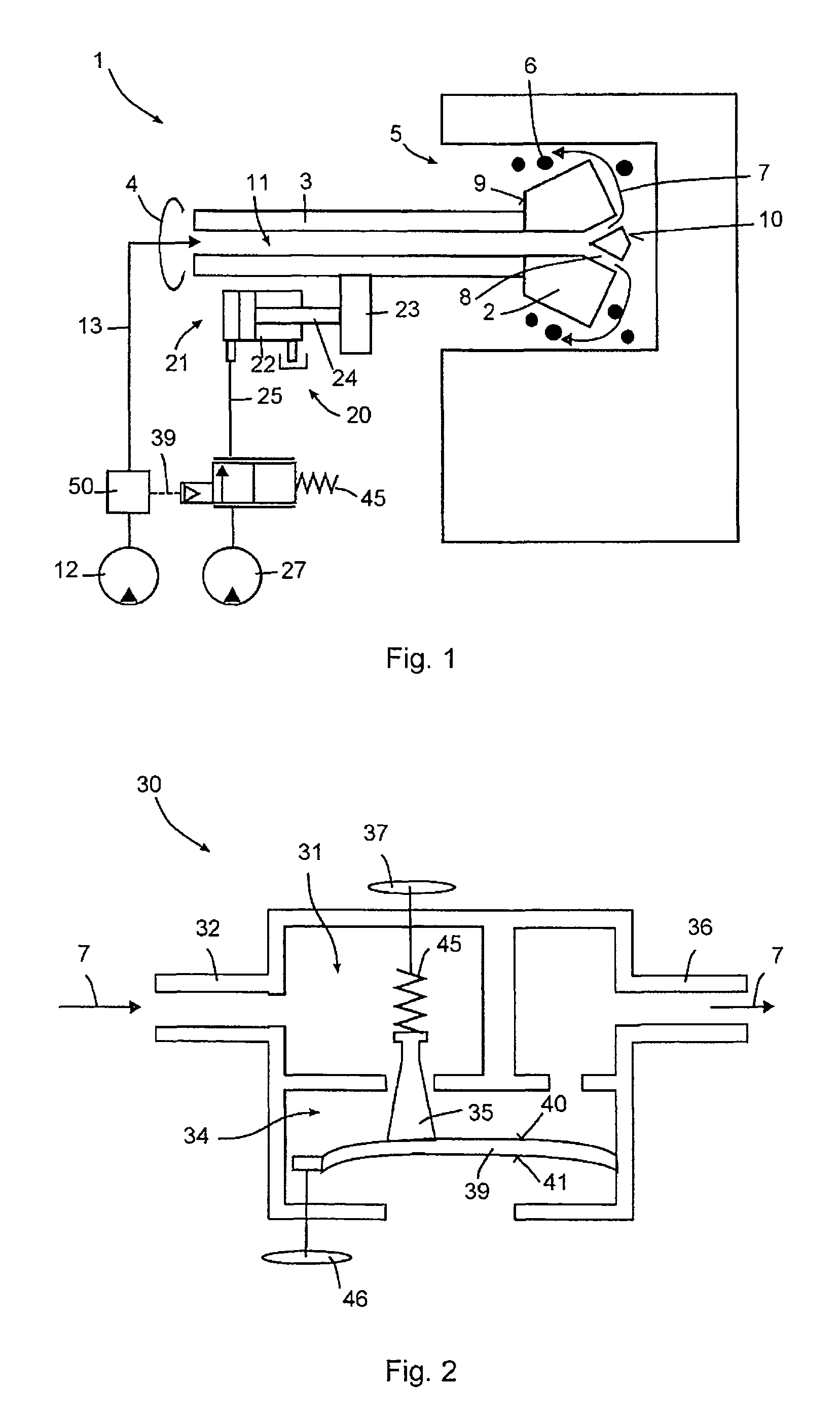
[0016]According to one embodiment of the present invention, the flow limiter includes a valve that prevents flow of the hydraulic fluid when the pressure applied to the adjusting member exceeds an upper threshold value. At a lower threshold value, the valve should be, preferably, completely open. In the simplest case, the control can take place just by opening and closing the valve. Supply elements, e.g., hysteresis elements, can improve the control characteristics, in particular, hysteresis elements that slow down opening of the valve.
[0017]According to a modified embodiment, the valve is formed as a proportional valve for adjusting the flow of the hydraulic fluid or the pressure at its outlet proportionally to the pressure applied to the adjusting member. The valve, in this case, operates with a smaller stroke and a uniform control mode. Thereby, a mechanical load applied to the valve can be reduced.

Problems solved by technology

The pressure of the rinsing fluid increases when the rinsing fluid is not able to expel the drillings with an adequate delivery rate.
As a result, the bore starts to clog.

Method used


Image

  • Drilling tool and drilling method
  • Drilling tool and drilling method
  • Drilling tool and drilling method

Examples


Embodiment Construction

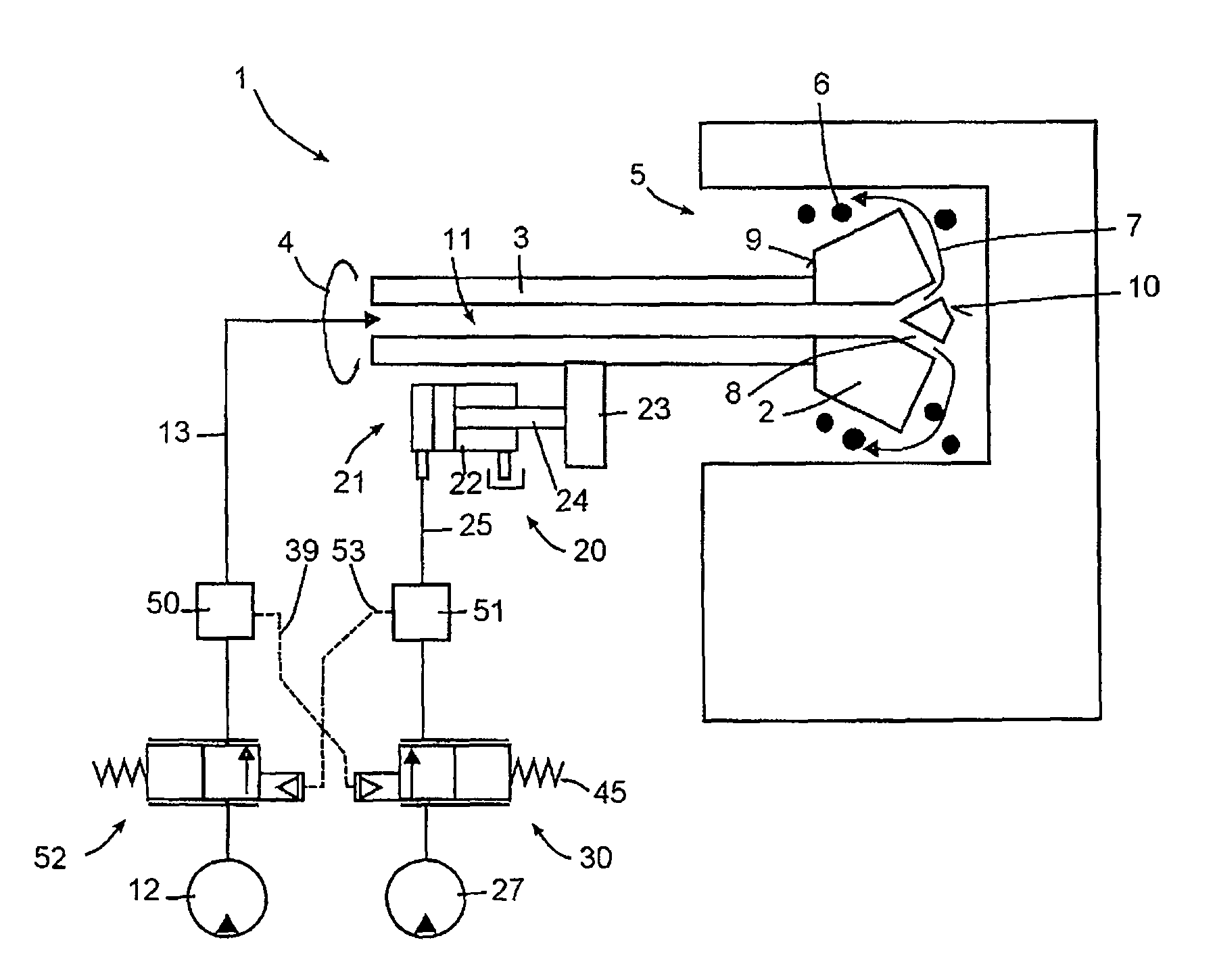
[0026]A drilling tool 1 according to the present invention, a first embodiment of which is schematically shown in FIG. 1, has a drilling head 2 secured on an anchor 3. The drilling tool 1 rotates the anchor 3 about a longitudinal axis 4 of the anchor 3. The drilling head 2 forms a bore 5 in a rock formation.

[0027]The produced drillings 6 are removed from the bore 5 with a rinsing fluid 7. The drilling head 2 has channels 8 which connect a rear side 9 of the drilling head 2 with its front side 10. The rinsing fluid 7 is fed to the drilling head 2 through a longitudinal channel 11 provided in the anchor 3. The rinsing fluid 7 is delivered by a delivery pump 12 through a conduit 13 connected with the hollow anchor 3. The drillings 6 are forced from the bore 5 by the rinsing fluid 7 sidewise of the drilling head 2. As rinsing fluid 7, water or another liquid can be used. Alternatively, a compressed air can be used. According to one of the embodiment, the air is not forced through but is...


PUM


Abstract

A drilling tool includes a hydraulically driven device (21) for advancing a drilling head (2) in a bore (5), and a flow limiter (30) arranged in a hydraulic conduit (25) of the advancing device (21) for adjusting an advancing speed of the drilling head (2) in the bore (5), with the flow limiter (30) having a pressure-actuated adjusting member (38) for adjusting flow of a hydraulic fluid in the hydraulic conduit means (25) in accordance with a flow volume of a rinsing fluid (7) for rinsing the bore.

Description

BACKGROUND OF THE INVENTION[0001]1. Field of the Invention[0002]The present invention relates to a drilling tool for and a drilling method of drilling bores in rock formations in mines.[0003]2. Description of the Prior Art[0004]In mines, the rock formation is formed of diverse layers. In addition to desired extraction products, e.g., coal, ore, the mine rock formations contain loam layers.[0005]A load applied to a drilling tool varies with varying of the rock formation layers. At a pure manual operation, the tool user should adapt an advancing speed of a drilling head to the layer sequence. In particular, in the loam layers, a slow advance is required so that the glutinous loam is rinsed out of the bore and would not set around the drilling head.[0006]In practice, a tool user has only an approximate knowledge of the position of separate layers. Therefore, the user is forced to work with a small advancing speed.[0007]U.S. Pat. No. 6,637,522 discloses an automated process that should ...

Claims


Application Information

Patent Timeline
Patent Type & Authority Patents(United States)
IPC IPC(8): E21B21/08E21B44/02
CPCE21B21/08E21B44/02E21B44/06
Inventor HEEMANN, KAYBOHN, UWELUDWIG, WOLFGANG
Owner HILTI AG
Learn More