Method for implanting an intervertebral disk prosthesis

a technology of intervertebral disk and prosthesis, which is applied in the field of implanting an intervertebral disk prosthesis, can solve the problems of not being able to fully implant the intervertebral space, not being able to achieve the effect of facilitating the intervertebral space, and difficult visual control

Inactive Publication Date: 2012-04-03
CERVITECH INC
View PDF111 Cites 12 Cited by
  • Summary
  • Abstract
  • Description
  • Claims
  • Application Information

AI Technical Summary

Benefits of technology

[0010]In a particularly preferred embodiment of the invention, the edge of the prosthesis cover plate extends beyond the dorsolateral limit of the associated connection surface. In this way, the cover plate, the prosthesis core and the connection or slide surfaces interacting on the cover plates and the prosthesis core can have an optimum size despite the set-back nature of the connection surface. These parts can therefore be designed, for example, roughly as a rectangular shape with rounded corners.

Problems solved by technology

This applies in particular when shaping the dorsolateral corners of the bearing surfaces, where visual control is more difficult than in the central dorsal region.
If one were to use a rectangular prosthesis, this would not be able to be inserted fully into the intervertebral space because its dorsal corners would strike against the bone material which has been left.
If the prosthesis corners are rounded, the circumstances are not much more favorable.
The prosthesis then protrudes ventrally beyond the vertebral bodies and may cause irritation of the esophagus or the large blood vessels located there.

Method used


Image

  • Method for implanting an intervertebral disk prosthesis
  • Method for implanting an intervertebral disk prosthesis
  • Method for implanting an intervertebral disk prosthesis

Examples


Embodiment Construction

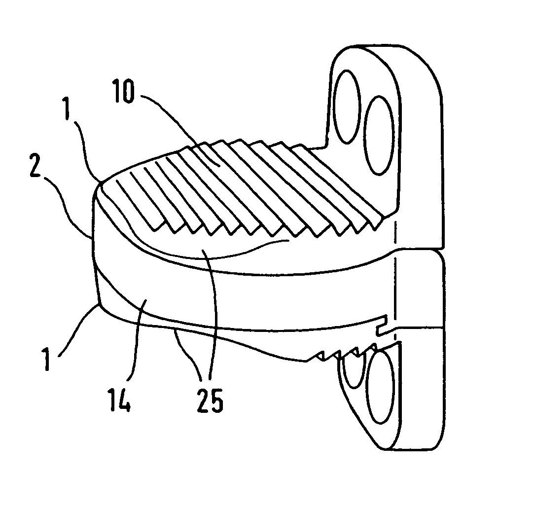
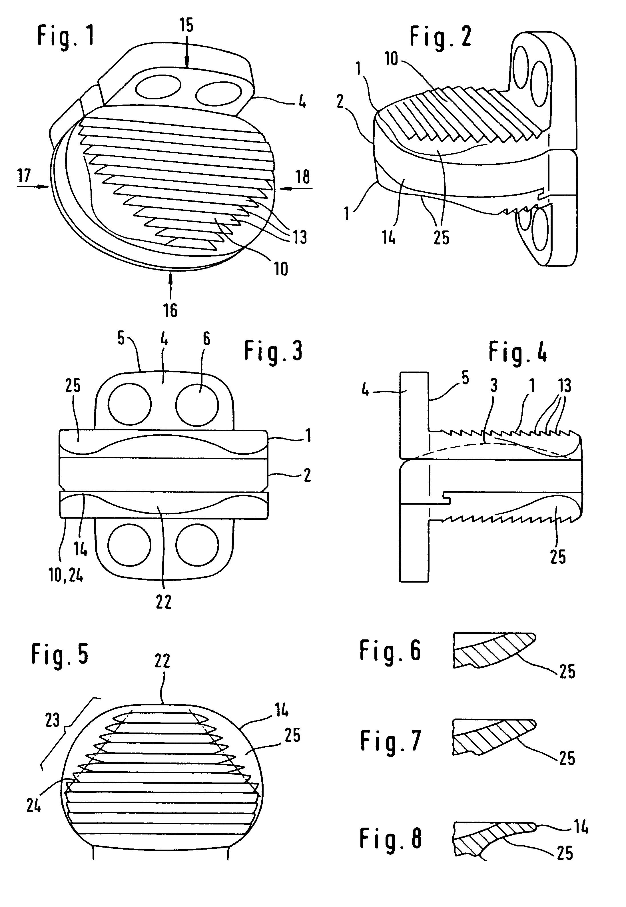
[0022]The prosthesis shown in FIGS. 1 to 8 consists of two cover plates 1 and of a prosthesis core 2. The inner face of one of the two cover plates can be provided as a mounting for the prosthesis core 2, while the other cover plate forms, with the prosthesis core, a spherical slide surface 3, for example. At the ventral edge of each cover plate there is a flange 4 whose dorsal face 5 is intended to bear on the ventral face of a vertebral body. The flange can have securing means, for example screw holes 6. Each prosthesis cover plate has a connection surface 10 for bearing on the associated vertebral body cover plate and on the bearing surface created by shaping the vertebral body, said connection surface 10 extending approximately parallel to the main plane of the cover plate. It is substantially flat, but can also have a slight curvature. It is equipped with teeth 13 and / or other means for connecting it securely in position to the bone, for example with a biologically active coati...


PUM


Abstract

A cervical intervertebral disk prosthesis has two cover plates, at least one of which is provided with a wedge-shaped connection surface for connection to a vertebral body and which is wider than it is deep. The dorsal edge of the connection surface may be set back from the dorsolateral edge of the cover plate having the connection surface and be connected to the dorsal edge protruding above it via a rounding or bevel.

Description

REFERENCE TO RELATED APPLICATION[0001]This application is a continuation of Ser. No. 10 / 407,946, filed Apr. 7, 2003 now U.S. Pat. No. 8,012,212.BACKGROUND OF THE INVENTION[0002]Endoprostheses for replacement of an intervertebral disk of the cervical spine are known (FR-A-2 718 635, EP-B-699 426) which consist of two cover plates and a joint core. The cover plates, which are arranged approximately parallel on both sides of the core, have connection surfaces which are intended for connection to the adjacent vertebral bodies. The cranial vertebral body cover plates, which are to be connected to a lower prosthesis cover plate, have a roughly rectangular shape. They are approximately flat and are delimited at the sides by edge serrations. The caudal vertebral body cover plates have extensive edge serrations at the ventral edge. These have to be removed before the prosthesis is fitted. It is also expedient for the vertebral body surfaces which are intended to bear on the prosthesis to be ...

Claims


Application Information

Patent Timeline
Patent Type & Authority Patents(United States)
IPC IPC(8): A61F2/44A61F2/30
CPCA61F2/4425A61F2002/30578A61F2002/30649A61F2002/30904
Inventor LINK, HELMUT D.KELLER, ARNOLDMCAFEE, PAUL C.
Owner CERVITECH INC
Why Eureka
Try Eureka