Tubular flow reactor and method of manufacturing polymeric resin fine particle

a technology of tubular flow reactor and fine particle, which is applied in the direction of clay mixing apparatus, transportation and packaging, rotary stirring mixer, etc., can solve the problems of increasing the initial plant investment of a large sized reactor, increasing the amount of energy consumption to make up for heat transfer capacity, and difficulty in downsizing the tubular flow reactor

Active Publication Date: 2012-04-03
KONICA MINOLTA BUSINESS TECH INC
View PDF13 Cites 20 Cited by
  • Summary
  • Abstract
  • Description
  • Claims
  • Application Information

AI Technical Summary

Benefits of technology

[0021]A tubular flow reactor of the present invention can maintain a plug flow property even though the tubular flow reactor is downsized, and when the tubular flow reactor is used for preparation of the resin fine particle via emulsion polymerization or the like, produced are excellent effects through which uniform resin particles exhibiting a narrow particle size distribution and a narrow molecular weight distribution are obtainable.

Problems solved by technology

The batch reactor produced problems such as large non-production time which is not related to a polymerization reaction, increased initial plant investment for a large sized reactor; and an increasing amount of energy consumption to make up for heat transfer capacity.
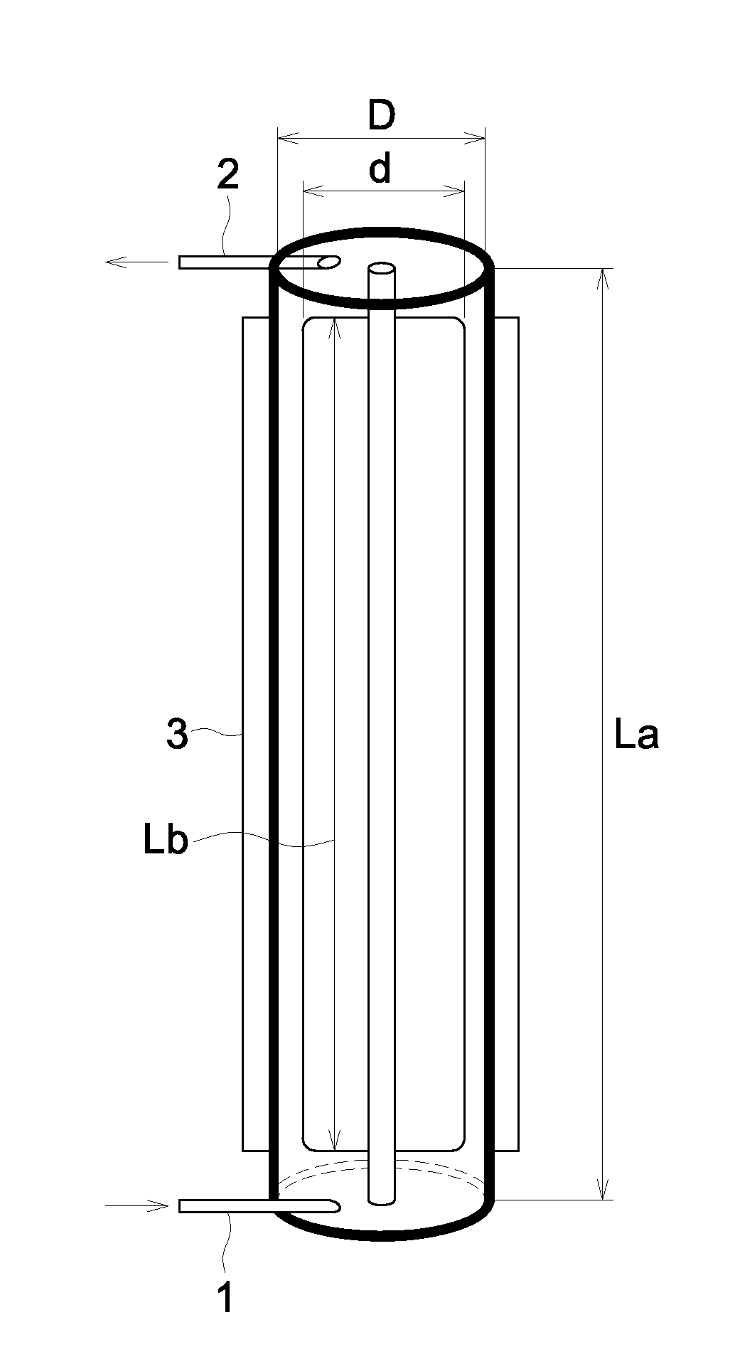
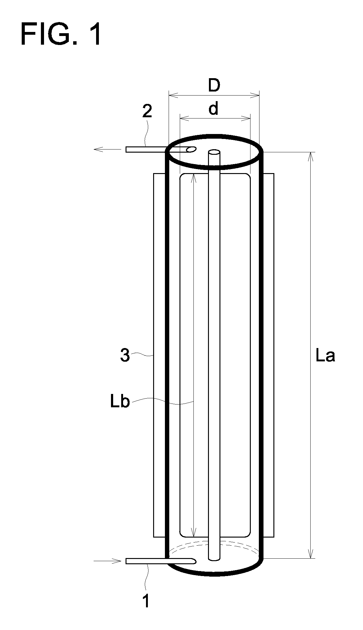
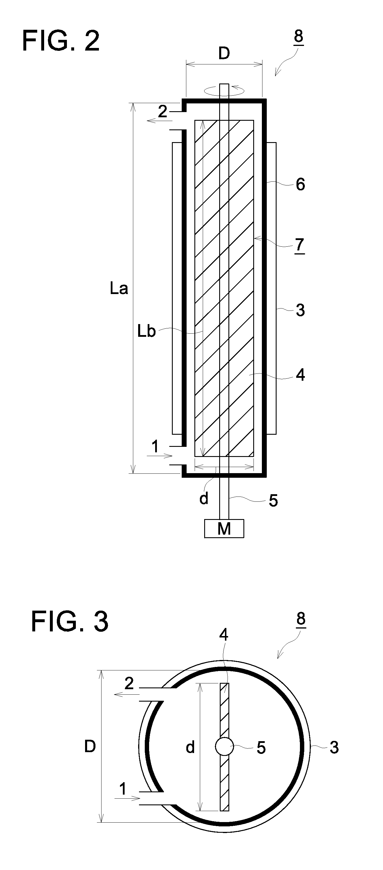
As a specific method to obtain a plug flow property, for example, provided is a method of making a ratio (relationship) (La / D) to be large (for example, exceeding 100), wherein the ratio is a ratio of length (La) of a cylindrical channel to inner diameter (D) of the cylindrical channel, but in such a case, difficulty in downsizing of the tubular flow reactor results.

Method used


Image

  • Tubular flow reactor and method of manufacturing polymeric resin fine particle
  • Tubular flow reactor and method of manufacturing polymeric resin fine particle
  • Tubular flow reactor and method of manufacturing polymeric resin fine particle

Examples


example 1

[0130]Resin fine particles were prepared by the following procedures, employing a continuous resin fine particle manufacturing apparatus shown in the foregoing FIG. 6.

(1) Preparation of Surfactant Solution

[0131]The following materials were mixed and dissolved to prepare a surfactant solution.

[0132]

Sodium dodecylsulfate 0.82 parts by weightDeionized water539.18 parts by weight

(2) Preparation of Polymerizable Monomer Solution

[0133]The following materials were mixed and dissolved to prepare a polymerizable monomer solution.

[0134]

Styrene67.7 parts by weightn-butyl acrylate19.9 parts by weightMethacrylic acid10.9 parts by weightt-octylmercaptan 2.2 parts by weight

(3) Preparation of Oil Droplet Dispersion

[0135]The polymerizable monomer solution prepared above was dispersed in the surfactant solution employing a mechanical dispersion apparatus (“US homogenizer 300T” manufactured by Nissei Corporation) so as to reach an oil droplet diameter of 100 nm, and an oil droplet dispersion was prepa...

examples 2-10

[0140]Resin fine particles were prepared similarly to preparation of Example 1, except that reactor 2 for which each dimension of the tubular flow reactor used in Example 1 was replaced by those described in Table 1 was employed. This is designated as “resin fine particles 2-9, and 13”.


PUM

PropertyMeasurementUnit
droplet diameteraaaaaaaaaa
temperatureaaaaaaaaaa
concentrationaaaaaaaaaa

Abstract

In the present invention, a tubular flow reactor can maintain a plug flow property even though the tubular flow reactor is downsized, and provided is the tubular flow reactor with which uniform resin fine particles exhibiting a narrow particle size distribution and a narrow molecular weight distribution can be prepared when the tubular flow reactor is used for preparation of the resin fine particle via emulsion polymerization or the like. Disclosed is a tubular flow reactor possessing a stirring blade and a cylindrical channel, wherein a ratio d / D is 0.3-0.9 when a diameter of the stirring blade is represented by d and an inner diameter of the cylindrical channel is represented by D, and a ratio Lb / La is 0.80-0.99 when a length of the stirring blade is represented by Lb and a length of the cylindrical channel is represented by La.

Description

[0001]This is a 371 of PCT / JP2009 / 053850 filed Mar. 2, 2009 which in turn claimed the priority of Japanese Patent Application No. 2008-065482 filed Mar. 14, 2008, both applications are incorporated by reference herein.TECHNICAL FIELD[0002]The present invention relates to a tubular flow reactor, and a method of preparing polymeric resin fine particles employing the tubular flow reactor.BACKGROUND[0003]As methods of preparing polymeric resin fine particles (resin fine particles) industrially via an emulsion polymerization method or a suspension polymerization method, known are methods of preparing those employing a batch type reactor or a continuous type reactor.[0004]The batch reactor produced problems such as large non-production time which is not related to a polymerization reaction, increased initial plant investment for a large sized reactor; and an increasing amount of energy consumption to make up for heat transfer capacity.[0005]On the other hand, it is advantageous in a conti...

Claims


Application Information

Patent Timeline
Patent Type & Authority Patents(United States)
IPC IPC(8): C08F2/00B01J19/18C08F220/12B01F7/16
CPCB01F7/00291B01F7/00633B01F7/00908B01F7/18B01J19/0066B01J19/1812C08F2/01B01J2219/00006B01J2219/00011B01J2219/00033B01J2219/00094B01J2219/00166B01J2219/00768Y10S526/909Y10S526/918B01F27/1125B01F27/50B01F27/191B01F27/90
Inventor SAITA, YASUHARUMAMINO, MASASHI
Owner KONICA MINOLTA BUSINESS TECH INC
Why Eureka
Try Eureka