Permanent magnet brushless machine with magnetic flux regulation

a permanent magnet, brushless technology, applied in the direction of windings, dynamo-electric components, magnetic circuit shapes/forms/construction, etc., can solve the problems of excessive weight, poor heat dissipation, and complex and costly machines of complex design

Active Publication Date: 2012-04-03
HAMILTON SUNDSTRAND CORP
View PDF2 Cites 9 Cited by
  • Summary
  • Abstract
  • Description
  • Claims
  • Application Information

AI Technical Summary

Problems solved by technology

However, such proposals have generally involved machines of complex and costly design that have excessive weight and poor heat dissipation.

Method used


Image

  • Permanent magnet brushless machine with magnetic flux regulation
  • Permanent magnet brushless machine with magnetic flux regulation
  • Permanent magnet brushless machine with magnetic flux regulation

Examples


Embodiment Construction

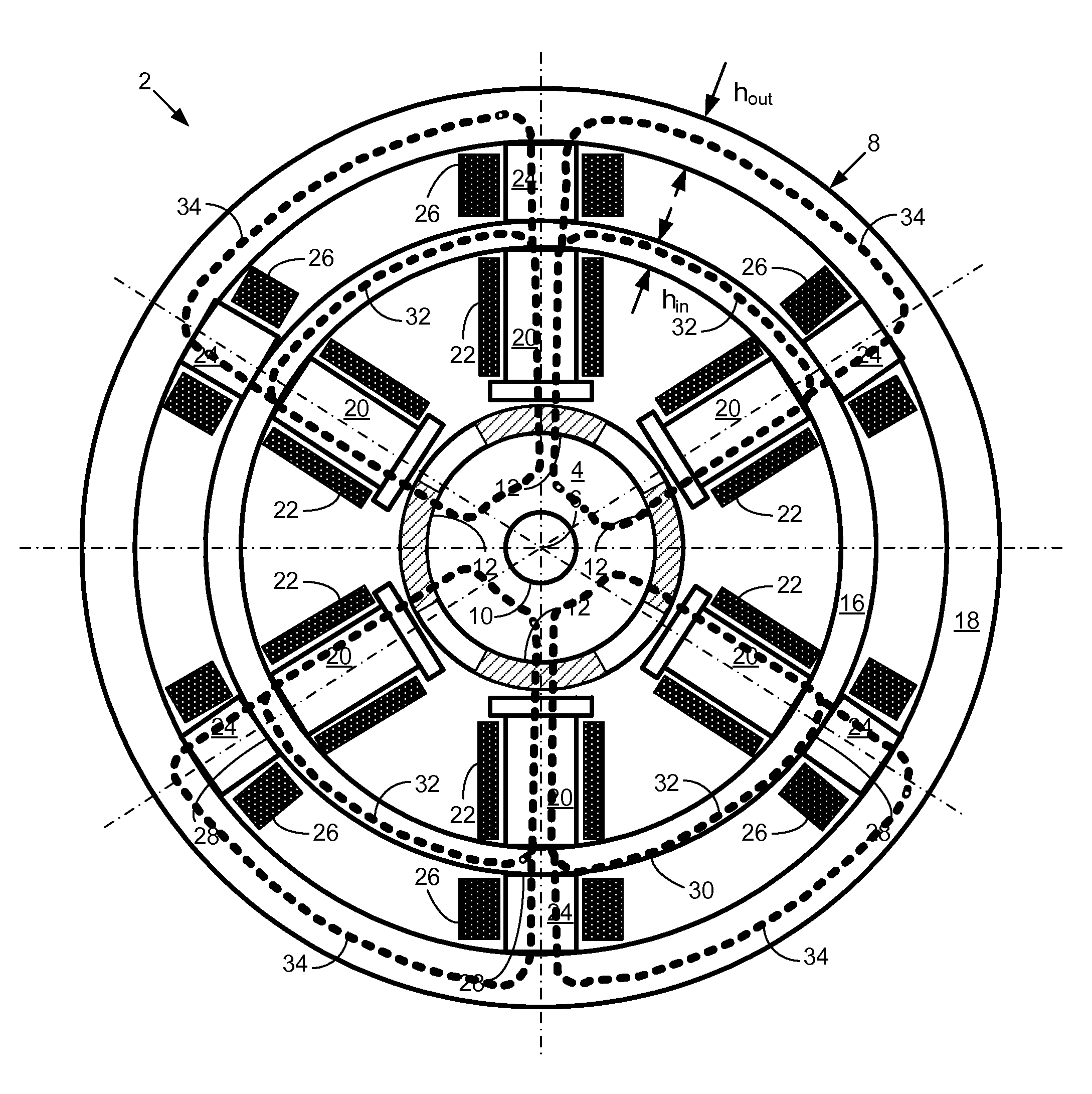
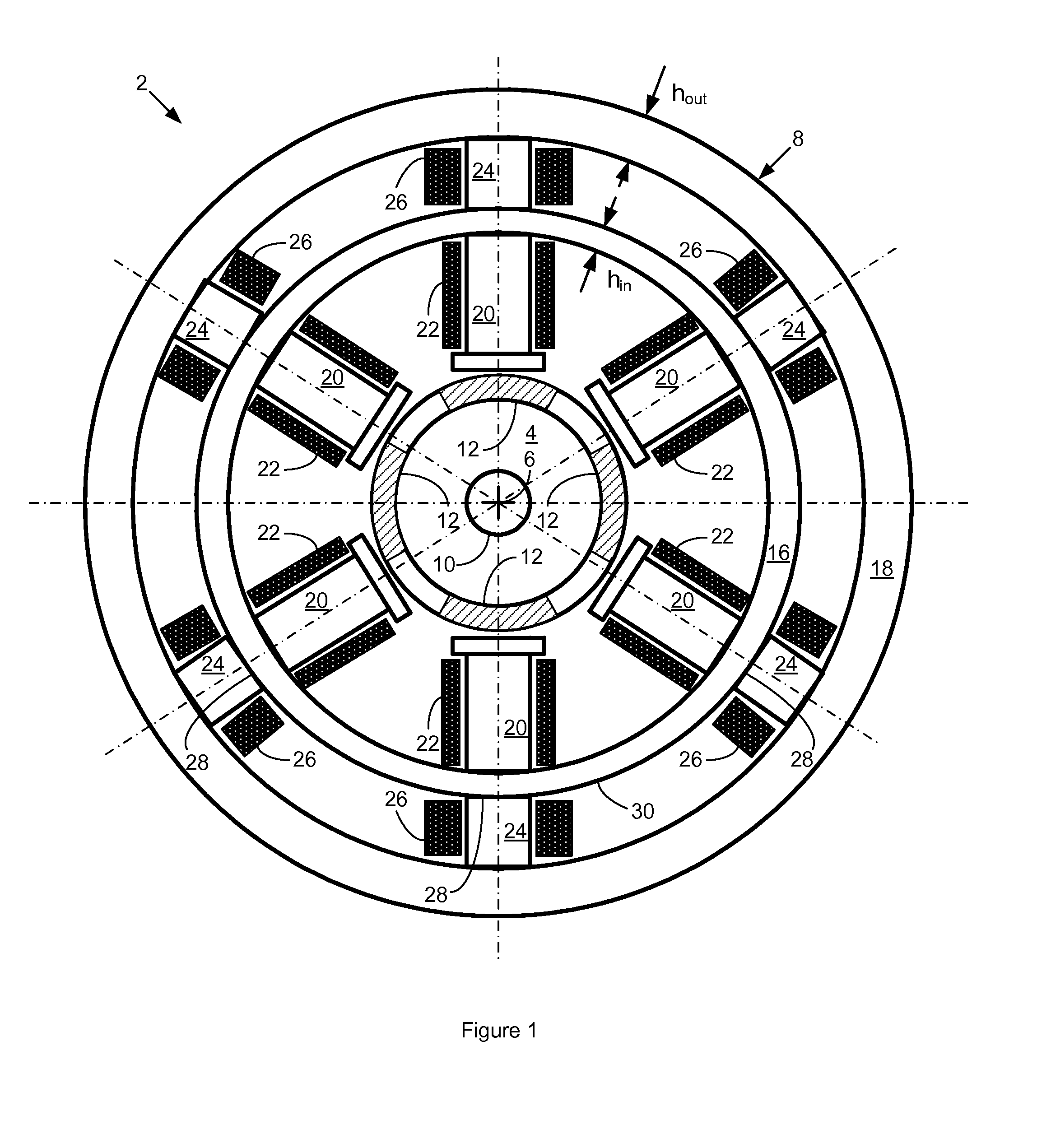
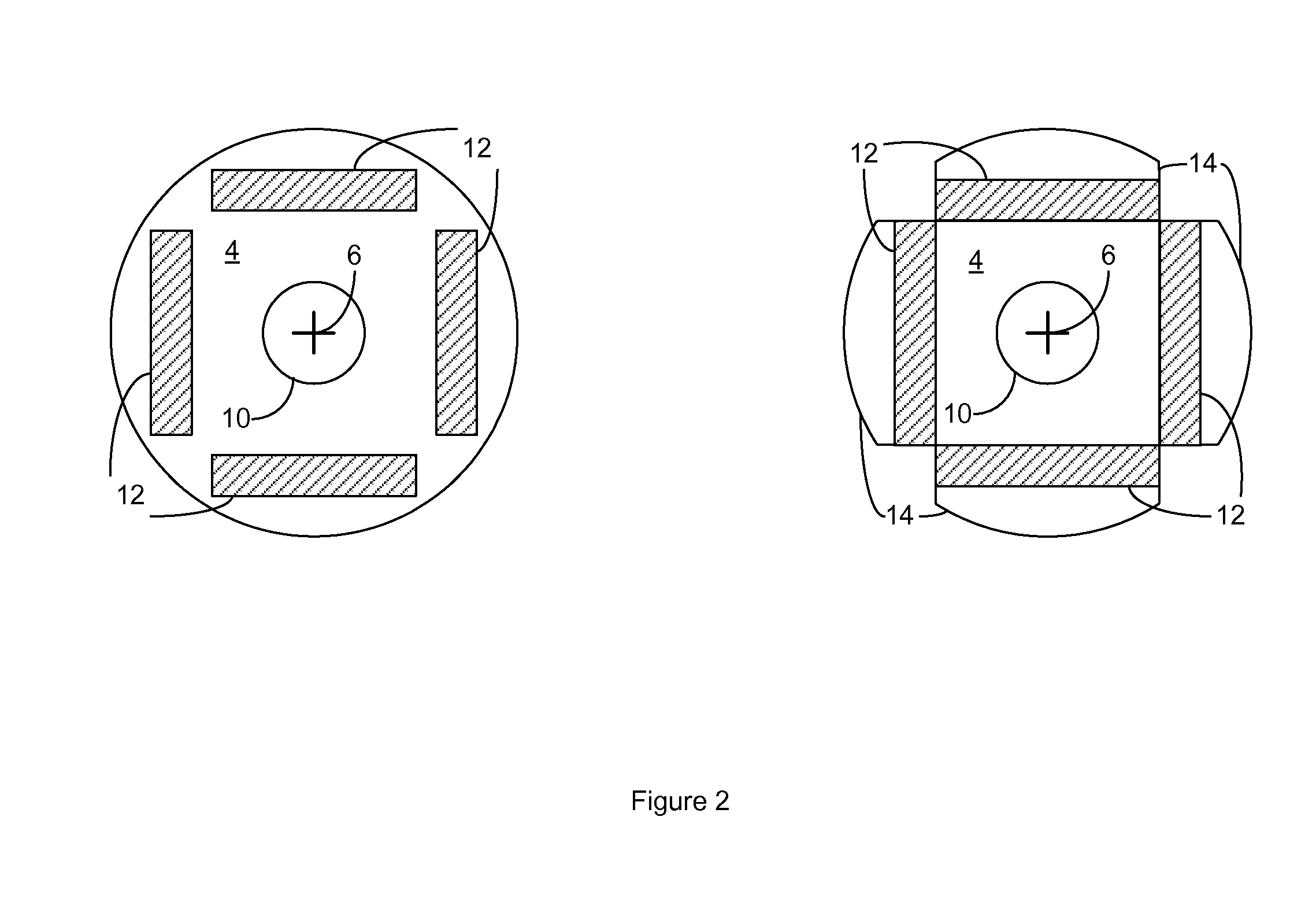
[0012]FIG. 1 is a cut-away end view of a PMM 2 according to a first possible embodiment of the invention. It comprises a PM rotor 4 that revolves about a rotor axis of rotation 6 and a stator 8. The rotor 4 typically rotates with a coupled drive shaft 10 that has an axis of rotation coincident with the rotor axis 6. By way of illustration only, the rotor 4 has four PM rotor poles 12 arranged about the rotor axis that comprise surface mounted PMs. The rotor 4 may have a different number of rotor poles 12, and the rotor poles 12 may have a different configuration. For instance, FIG. 2 shows the rotor 4 with two alternate configurations for the rotor poles 12, one with the rotor poles 12 comprising PMs embedded in the rotor 4 and another with the rotor poles 12 comprising PMs mounted with associated ferromagnetic pole faces 14.

[0013]The stator 8 has two generally cylindrical yokes, an inner yoke 16 and an outer yoke 18. The inner yoke 16 is proximate the PM rotor 4 and it has associate...


PUM


Abstract

A permanent magnet machine (PMM) has a generally cylindrical permanent magnet (PM) rotor that has multiple PM rotor poles arranged around a rotor axis of rotation; and a stator with two generally cylindrical and concentric yokes, an inner yoke proximate the PM rotor with associated multiple inner poles and inner armature windings suitable for multiphase alternating current operation that form a PMM magnetic flux circuit, an outer yoke with associated multiple outer poles and outer control windings suitable for connection to a direct current source, with distal ends of the outer poles in contact with the inner yoke to form an external magnetic flux circuit that diverts magnetic flux from the PMM magnetic flux circuit; wherein application of increasing direct current to the outer windings results in increased magnetic reluctance of the external magnetic flux circuit, thereby causing the external magnetic flux circuit to divert less magnetic flux from the PMM magnetic flux circuit.

Description

FIELD OF THE INVENTION[0001]The invention relates to electric machines that have a permanent magnet rotor, and more particularly to permanent magnet machines that have a control winding for magnetic flux regulation.BACKGROUND OF THE INVENTION[0002]There have been various proposals for multiphase electric machines of the permanent magnet type that include magnetic flux regulation by way of a control current to regulate their electromotive force (EMF) in a generating mode and developed torque in a motor mode. However, such proposals have generally involved machines of complex and costly design that have excessive weight and poor heat dissipation.SUMMARY OF THE INVENTION[0003]The invention generally comprises a permanent magnet machine (PMM) comprising: a generally cylindrical permanent magnet (PM) rotor that comprises multiple PM rotor poles arranged around a rotor axis of rotation; and a stator with two generally cylindrical and concentric yokes, an inner yoke proximate the PM rotor ...

Claims


Application Information

Patent Timeline
Patent Type & Authority Patents(United States)
IPC IPC(8): H02K21/00
CPCH02K21/046
Inventor GIERAS, JACEK F.ROZMAN, GREGORY I.KOENIG, ANDREAS C.
Owner HAMILTON SUNDSTRAND CORP
Why Eureka
Try Eureka