Communication system

a communication system and wireless technology, applied in the field of wireless communication systems, can solve the problems of unexpectedly low data gain, weakening of signal strength, unexpectedly poor correspondence between predicted and simulated gain, etc., and achieves low processing cost, simple determination of transmit power, and equal sinr performance

Active Publication Date: 2012-04-03
FUJITSU LTD
View PDF97 Cites 206 Cited by
  • Summary
  • Abstract
  • Description
  • Claims
  • Application Information

AI Technical Summary

Benefits of technology

[0019]Thus, preferred embodiments of the present invention seek to maintain or achieve a “balance” in a measure of the quality of a communication signal being received at the or each intermediate apparatus and a measure of the quality of a communication signal being received at a destination apparatus. Preferably, the determining means is operable to determine a change in the transmit power of one or more of the apparatuses which are operable to transmit a communication signal present communication system embodying the present invention, in order to reduce or prevent substantial imbalance (i.e. achieve or maintain a substantial “balance”) between a measure of the quality of a communication signal received at the intermediate apparatus and a measure of the quality of a communication signal received at the destination apparatus.
[0085]The desired value may be the value of the indicator of the quality of a communication signal derived by the destination apparatus which is at, or close to, the target value set by the destination apparatus, and when the system is substantially balanced (i.e. a measure of a quality of a communication signal received at the destination apparatus is in balance with a measure of a quality of communication signal received at the, or each, intermediate apparatus). Thus, embodiments of the first aspect of the present invention may be advantageously used to maintain the quality of the communication signal received by the destination apparatus at, or near, the target value set by the destination apparatus. Thereafter, it may be necessary for embodiments of a second aspect of the present invention to optimise the systems ensuring a balance is achieved between the destination apparatus and the or each intermediate apparatus.

Problems solved by technology

It is known that the occurrence of propagation loss, or “pathloss”, due to the scattering or absorption of a radio communication as it travels through space, causes the strength of a signal to diminish.
However, simulations carried out to test the applicability of multi-hop communication systems have revealed unexpectedly low gains in throughput of data.
However, even when predictions are based on a more accurate reflection of the pathloss parameters likely to be encountered in the real world, simulations of multi-hop systems have revealed unexpectedly poor correspondence between the predicted and simulated gain.
Alternatively, an imbalance may be apparent when a comparison is made via a mapping function.
If no adjustment is made to the transmit power, then significant excess transmit power (i.e. transmit power exceeding that required to achieve a good, or target, signal quality at the destination apparatus and / or the intermediate apparatus) will result.
Rather than serving to further increase the gain achieved by a multi-hop communication as compared to a direct communication between a source apparatus and a destination apparatus, this excess transmit power will merely increase interference levels leading to a deterioration in the quality of the communication link.
This deterioration will tend to counteract the potential gain of a multi-hop system which accounts for the poor simulation results of previously considered multi-hop communication systems.
Furthermore, the overall throughput across a two-hop network (for example) is limited by the lower of: the number of data packets received at the intermediate apparatus and the number of data packets received at the destination apparatus.
Thus, in effect, the receiver which receives the lowest quality communication signal within a multi-hop system forms a “bottle neck” for data packet transmission, thereby wasting capacity for data transfer on other links within the multi-hop system.
An increase the transmit power at a transmitter which does not serve to improve the lowest quality communication signal, will result in additional excess transmit power.
Consequently, a further degradation is experienced in the performance of the system.
It can be seen that as the transmit power of the base station is increased beyond an optimal point, then a significant degradation in gain will be experienced despite the emission of more signal energy.
There are a number of different events which, if they arise, can potentially lead to an “imbalance” (i.e. a difference between a measure of the quality of a communication signal received at the destination apparatus and a measure of the quality of a communication signal received at the or each intermediate apparatus) in a multi-hop system:i) The pathloss arising over one of the links changes.
In the case of a multi-hop system, merely adjusting the transmit power of one apparatus in order to accommodate a change in target of one of the receiving apparatuses, will lead to an imbalance within the system.
The imbalance may arise due to a change in pathloss between the base station and the intermediate apparatus.

Method used


Image

  • Communication system
  • Communication system
  • Communication system

Examples


Embodiment Construction

)

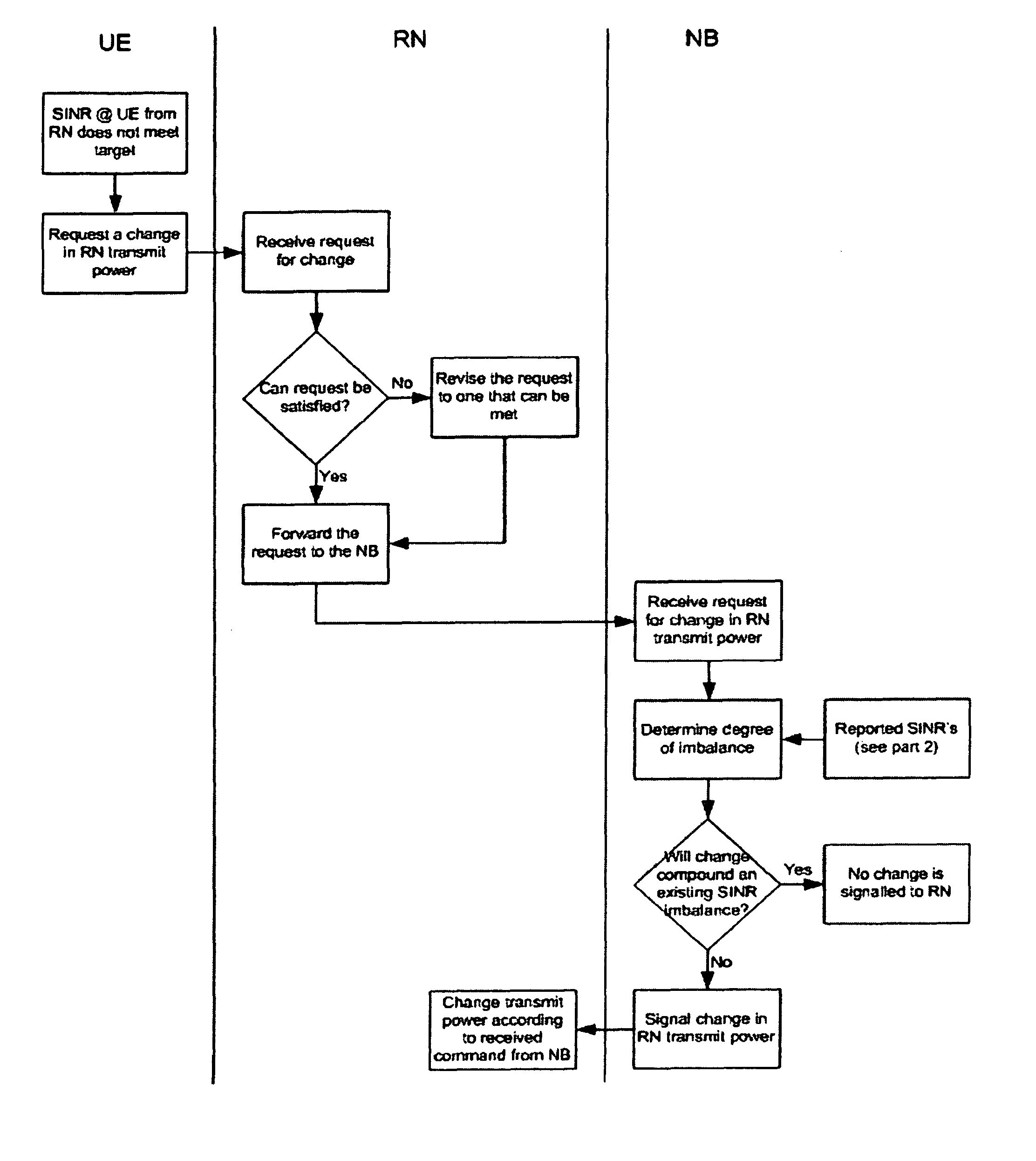
[0104]An example of an algorithm which implements an embodiment of the first aspect of the present invention will now be described with reference to FIG. 3 in which the source apparatus comprises a node-B (NB), the intermediate apparatus comprises a relay node (RN) is of the regenerative type, and the destination apparatus comprises a user equipment (UE). The destination user equipment continually monitors the SINR and derives indicators of the SINR and the variation from target SINR.

[0105]The details of the algorithm are summarized as follows:

[0106]

Downlink Algorithm 2: Part 1Trigger: RN receives request for change in RN transmit power from UEAlgorithm InputRequired byOriginRequest for change inNBChange derived in UE, modifiedRN Transmit Powerat RN and signalled toSINR at UE (see part 2)NBSINR at RN (see part 2)NBDestination &Algorithm OutputDerivationSignalling RequirementChange in RNRelativeDerived at UE, checked by RN,transmit powerchangeapproved by NB and actioned byRN

[0107]Th...


PUM


Abstract

The present application relates to a wireless communication system and related methods and apparatuses for transmitting a signal from a source apparatus to a destination apparatus, via at least one intermediate apparatus. In particular, the present invention relates to techniques which seek to improve the throughput of data in multi-hop communication systems.

Description

CROSS-REFERENCE TO RELATED APPLICATIONS[0001]This application is a divisional of U.S. patent application Ser. No. 11 / 453,839, filed Jun. 16, 2006, now pending, the contents of which are hereby incorporated by reference in their entirety.FIELD[0002]The present invention relates to a wireless communication system and related methods for transmitting a signal from a source apparatus to a destination apparatus, via at least one intermediate apparatus. In particular, the present invention relates to techniques which seek to improve the throughput of data in multi-hop communication systems.BACKGROUND OF THE INVENTION[0003]It is known that the occurrence of propagation loss, or “pathloss”, due to the scattering or absorption of a radio communication as it travels through space, causes the strength of a signal to diminish. Factors which influence the pathloss between a transmitter and a receiver include: transmitter antenna height, receiver antenna height, carrier frequency, clutter type (u...

Claims


Application Information

Patent Timeline
Patent Type & Authority Patents(United States)
IPC IPC(8): H04B7/15H04B3/36H04B7/14H04B7/185H04B7/00H04B17/40H04W52/24H04W52/34H04W52/46H04W88/04
CPCH04W52/24H04W52/34H04W52/46H04B7/2606H04W88/04Y02B60/50H04W84/18Y02D30/70
Inventor HART, MICHAEL JOHN
Owner FUJITSU LTD
Why Eureka
Try Eureka