Transmission power balancing in multi-hop communication systems

a communication system and multi-hop technology, applied in the field of communication systems, can solve the problems of unexpectedly low data throughput gain, weakening of signal strength, unexpectedly poor correspondence between predicted and simulated gain, etc., and achieve the effect of reducing or preventing an imbalance and simple determination of transmit power

a communication system and multi-hop technology, applied in the field of communication systems, can solve the problems of unexpectedly low data throughput gain, weakening of signal strength, unexpectedly poor correspondence between predicted and simulated gain, etc., and achieve the effect of reducing or preventing an imbalance and simple determination of transmit power

US7865146B2Inactive Publication Date: 2011-01-04FUJITSU LTD

Image

  • Transmission power balancing in multi-hop communication systems
  • Transmission power balancing in multi-hop communication systems
  • Transmission power balancing in multi-hop communication systems

Examples


Embodiment Construction

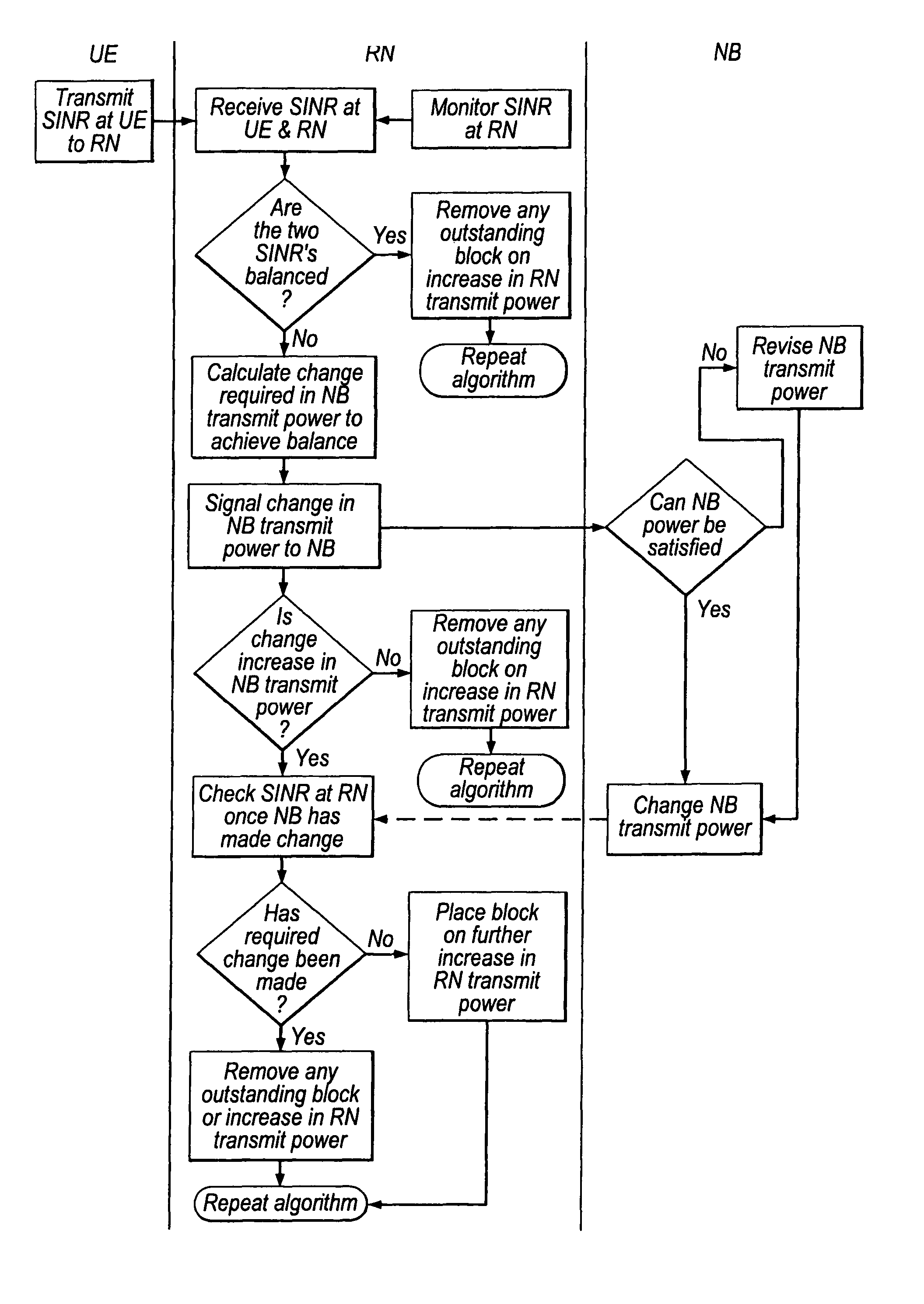
[0100]An example of an algorithm which implements an embodiment of the first aspect of the present invention will now be described with reference to FIG. 3A in the case of downlink transmission in which the source apparatus comprises a node-B (NB), the intermediate apparatus comprises a relay node (RN) which is of the regenerative type, and the destination apparatus comprises a user equipment (UE). The user equipment continually monitors the SINR and derives indicators of the SINR and the variation from target SINR. The destination apparatus is provided with an indicator deviation detection means for detecting a change in one or both of these indicators. The intermediate apparatus is provided with a control means according to an embodiment of the first aspect of the present invention.

[0101]The details of the algorithm are summarised as follows:

[0102]

Downlink Algorithm 3: Part 1Trigger: RN receives request for change in RN transmit power from UEAlgorithm InputRequired byOriginRequest...


PUM


Abstract

The present application relates to a wireless communication system and related methods and apparatuses for transmitting a signal from a source apparatus to a destination apparatus, via at least one intermediate apparatus. In particular, the present invention relates to techniques which seek to improve the throughput of data in multi-hop communication systems.

Description

BACKGROUND OF THE INVENTION[0001]The present invention relates to a communication system and related methods for transmitting a signal from a source apparatus to a destination apparatus, via at least one intermediate apparatus. In particular, the present invention relates to techniques which seek to improve the throughput of data in multi-hop communication systems.[0002]It is known that the occurrence of propagation loss, or “pathloss”, due to the scattering or absorption of a radio communication as it travels through space, causes the strength of a signal to diminish. Factors which influence the pathloss between a transmitter and a receiver include: transmitter antenna height, receiver antenna height, carrier frequency, clutter type (urban, sub-urban, rural), details of morphology such as height, density, separation, terrain type (hilly, flat). The pathloss L (dB) between a transmitter and a receiver can be modelled by:L=b+10n log d  (A)Where d (meters) is the transmitter-receiver ...

Claims


Application Information

Patent Timeline
04 Jan 2011
Publication
US7865146B2
IPC
H04B17/00; H04B7/00; H04W52/24; H04W52/34; H04W52/38; H04W88/04
CPC
H04W52/241; H04W52/242; H04W52/346; H04W52/38; H04B7/2606; H04W88/04; H04W52/46
Inventors
HART, MICHAEL JOHN