Mask assembly and method of fabricating the same

a mask and assembly technology, applied in the field of mask assembly, can solve the problems of lowering the positional precision of the mask assembly, difficult alignment and welding of the stick pattern mask, and moisture diffraction into the substrate, and achieves the effect of easy welding and high positional precision

Active Publication Date: 2012-04-10
SAMSUNG DISPLAY CO LTD
View PDF12 Cites 17 Cited by
  • Summary
  • Abstract
  • Description
  • Claims
  • Application Information

AI Technical Summary

Benefits of technology

[0011]The present invention provides a mask assembly and a method of fabricating the same in which a tensile welding portion extending from a pattern portion of a pattern mask with patterns arranged in a matrix is structurally changed so that the positions of patterns disposed in neighboring rows or columns may not be readjusted due to a corrective welding process. As a result, the pattern mask may be easily welded to a mask frame, and the mask assembly may be fabricated with high positional precision.

Problems solved by technology

In this case, moisture may diffuse into the substrate during the etching process.
However, it is necessary to prevent formation of a gap between the stick pattern masks, and aligning and welding the stick pattern masks are not easy due to the movement of the stick pattern masks.
However, when corrective welding is performed in order to precisely align patterns arranged in each row or column, the positions of patterns disposed in neighboring rows or columns are readjusted, thereby lowering positional precision of the mask assembly and increasing a stain failure rate.
A stain failure occurs when the mask patterns in a mask assembly are not fully aligned and a gap exists between neighboring mask patterns, causing undesirable deposition portions through the gap during a subsequent deposition process, and thus resulting in a stain on a substrate.

Method used


Image

  • Mask assembly and method of fabricating the same
  • Mask assembly and method of fabricating the same
  • Mask assembly and method of fabricating the same

Examples


Embodiment Construction

[0019]The present invention will be described more fully hereinafter with reference to the accompanying drawings, in which exemplary embodiments of the invention are shown. The same reference numerals are used to denote the same elements throughout the specification. It will also be understood that when a portion is referred to as being “connected to” another portion, it can be directly connected to the other portion or electrically connected to the other portion by intervening a third portion therebetween. In the drawings, the thicknesses of layers and regions are exaggerated for clarity.

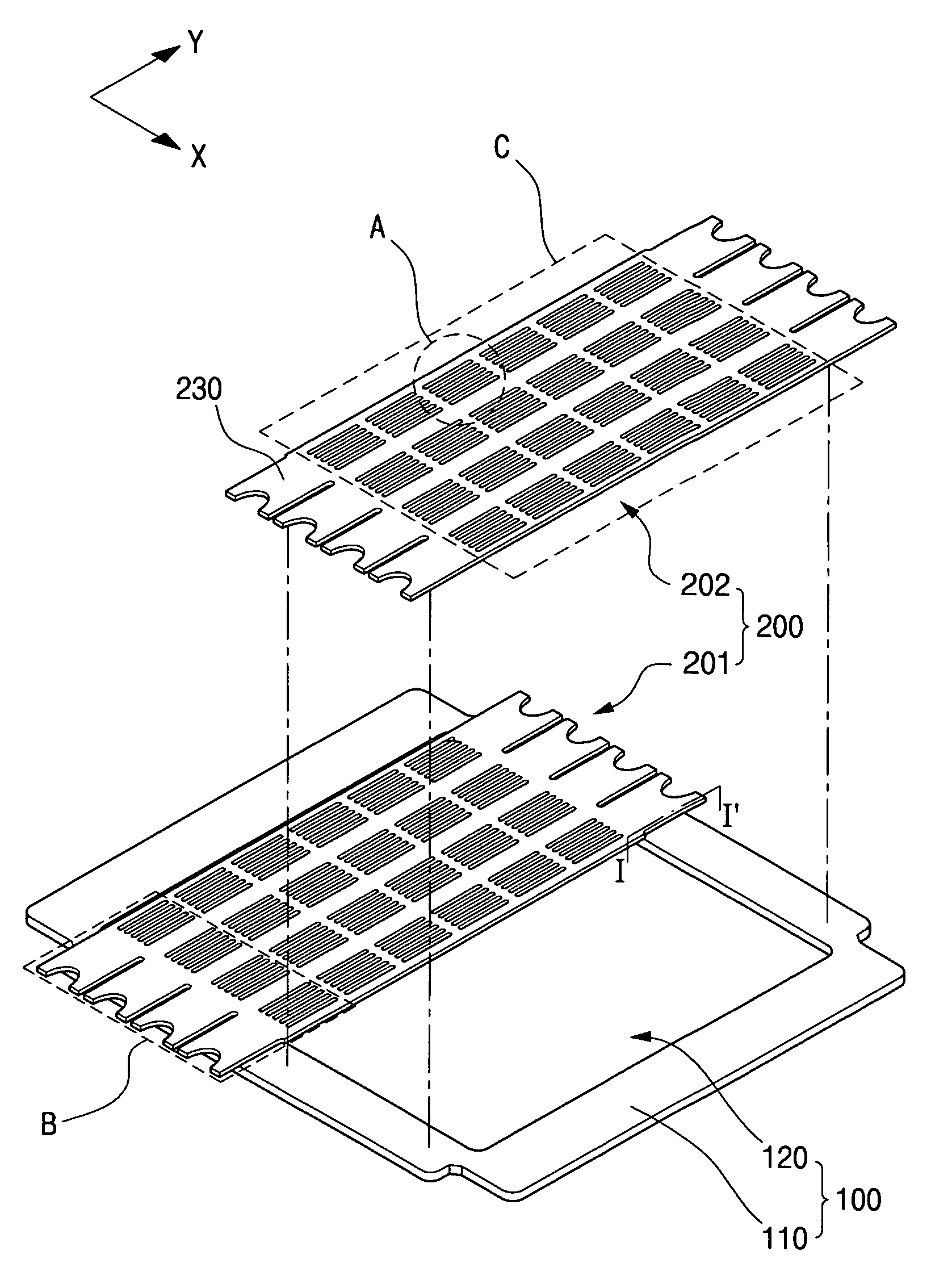
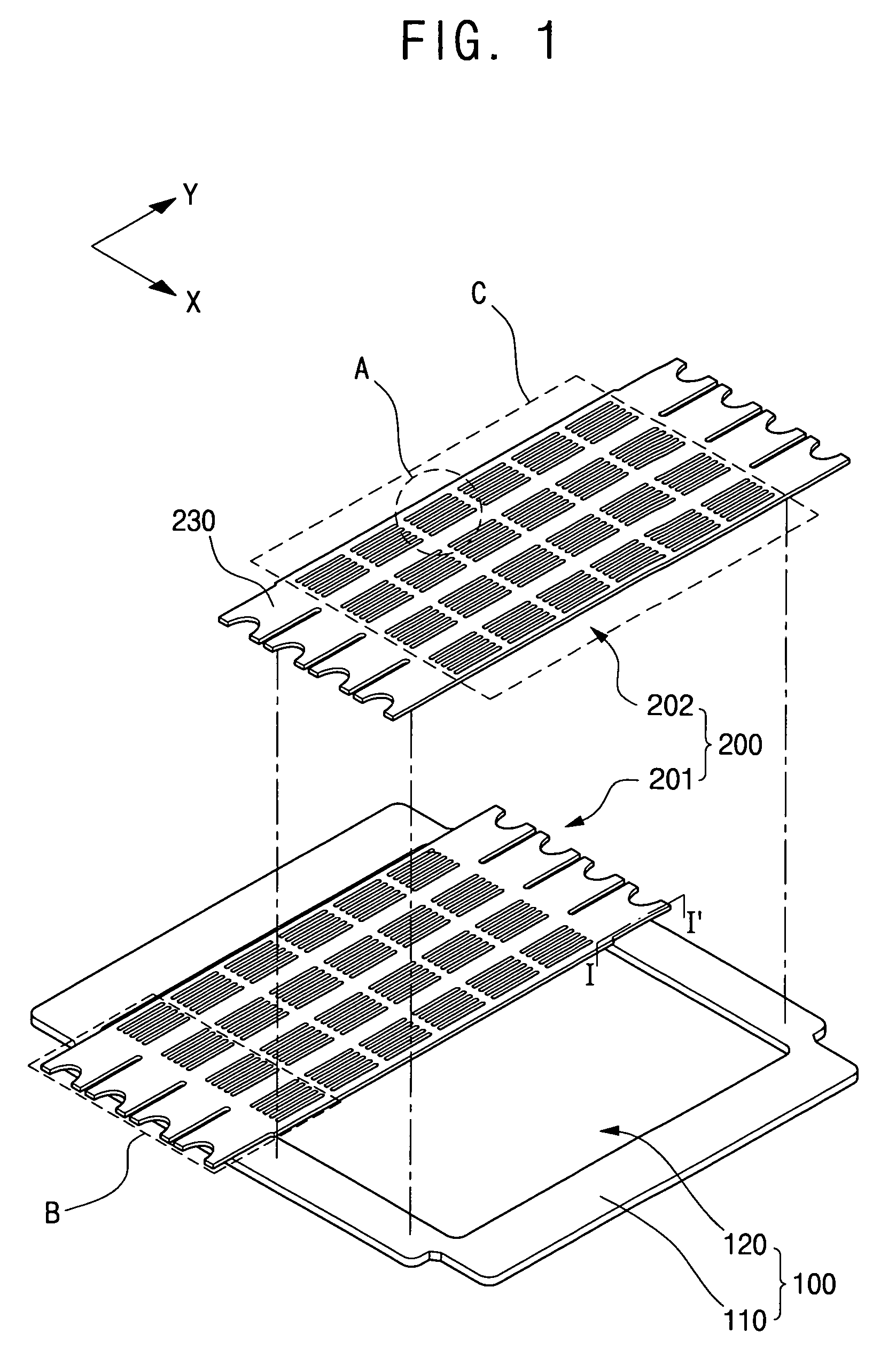
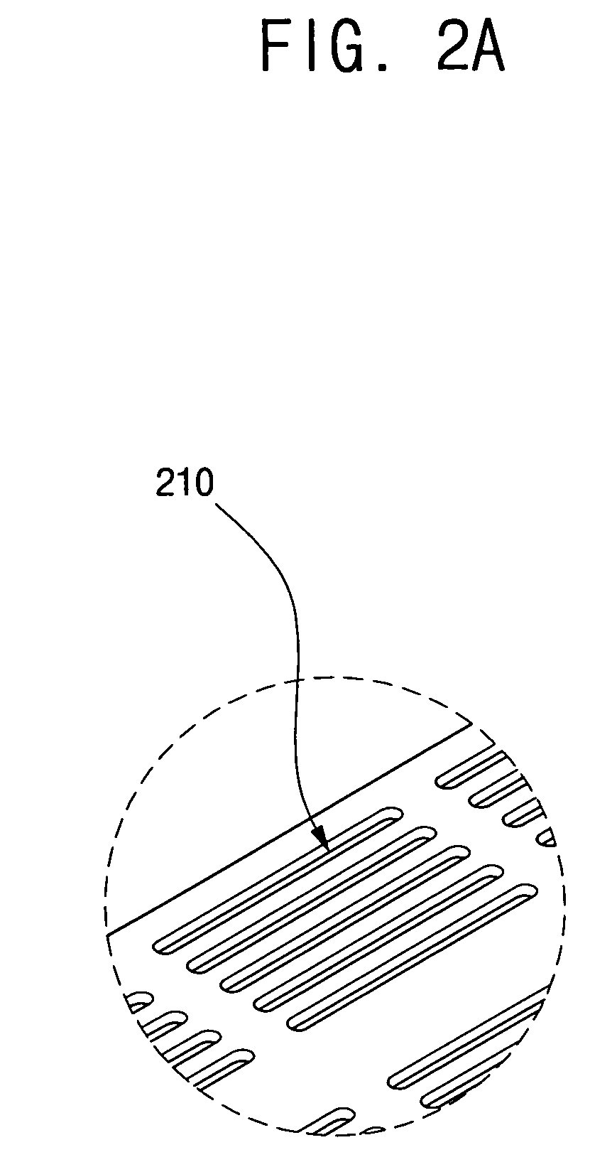
[0020]FIG. 1 is an exploded perspective view of a mask assembly according to an exemplary embodiment of the present invention, FIG. 2A is an enlarged perspective view of a region “A” of FIG. 1, illustrating a pattern of the mask assembly of FIG. 1, and FIG. 2B is an enlarged plan view of a region “B” of FIG. 1, illustrating a welding region between a pattern mask and a mask frame in the mask assemb...


PUM

PropertyMeasurementUnit
distanceaaaaaaaaaa
weightaaaaaaaaaa
luminanceaaaaaaaaaa

Abstract

In a mask assembly and a method of fabricating the same, when the mask assembly is fabricated by tensile welding a pattern mask to a mask frame, a tensile welding portion of the pattern mask welded to the mask frame is structurally changed. Thus, the pattern mask can be easily welded to the mask frame, and patterns of the pattern mask can be precisely aligned, thereby minimizing stain failure rate due to the mask assembly. The mask assembly includes: a mask frame including an opening and a support; and a pattern mask including a pattern portion having a plurality of patterns arranged in a matrix and a plurality of tensile welding portions extending from the pattern portion in a first direction and spaced apart from each other in a second direction perpendicular to the first direction. The method includes: providing a mask frame, a support, and a pattern mask as described above; disposing the pattern mask and the mask frame in a unique manner; combining the pattern mask with the mask frame by welding; measuring an aligned state of the pattern arranged in the first direction of the pattern mask; and welding a tensile welding portion using a secondary welding process according to an aligned state.

Description

CLAIM OF PRIORITY[0001]This application makes reference to, incorporates the same herein, and claims all benefits accruing under 35 U.S.C. §119 from an application for earlier filed in the Korean Intellectual Property Office on the 28 May 2008 and there duly assigned Serial No. 10-2008-0049748.BACKGROUND OF THE INVENTION[0002]1. Technical Field[0003]The present invention relates to a mask assembly and a method of fabricating the same and, more particularly, to a mask assembly and a method of fabricating the same in which, when the mask assembly is fabricated by tensile welding a pattern mask to a mask frame, a tensile welding portion of the pattern mask welded to the mask frame is structurally changed to facilitate the welding of the pattern mask to the mask frame and fine alignment of a pattern of the pattern mask, thereby minimizing a stain failure rate due to the mask assembly.[0004]2. Related Art[0005]A flat panel display device (FPD) has been employed as a display device which ...

Claims


Application Information

Patent Timeline
Patent Type & Authority Patents(United States)
IPC IPC(8): B05C1/00C23C16/00B05C11/11B05B15/04
CPCB23K31/02B23K2201/18B23K2201/24B23K2203/02Y10T428/24273B23K2203/14B23K2203/18Y10T428/24314B23K2203/10B23K2101/18B23K2101/24B23K2103/02B23K2103/05B23K2103/10B23K2103/14B23K2103/15B23K2103/18B23K2103/26H05B33/10C23C14/04
Inventor KO, JUNG-WOO
Owner SAMSUNG DISPLAY CO LTD
Why Eureka
Try Eureka