Engine fuel supply system

a fuel supply system and engine technology, applied in the direction of liquid fuel feeders, machines/engines, mechanical equipment, etc., can solve the problems of deteriorating the function of the diesel particulate filter, difficulty in starting the engine, and difficulty in discharge of exhaust gas, so as to reduce the pressure raising capacity, and reduce the size of the dual-purpose pump 60

Inactive Publication Date: 2012-04-10
KOMATSU LTD
View PDF13 Cites 5 Cited by
  • Summary
  • Abstract
  • Description
  • Claims
  • Application Information

AI Technical Summary

Benefits of technology

[0056]According to the first aspect of the invention, the system cost can be reduced, since both the air removal from the cylinder fuel supply passage 10 and the fuel supply into the exhaust pipe 4 can be performed by using the dual-purpose pump 60. According to the second aspect of the invention, as shown in FIG. 5, a supply passage 10b on a suction port 1b side of the fuel pump (feed pump) 1 in the cylinder fuel supply passage 10 is communicated with the suction port 60b of the dual-purpose pump 60 by a first fuel suction passage 80.
[0063]On the other hand, air removal from the cylinder fuel supply passage 10 is performed principally when the engine 2 is not in operation. According to the second aspect of the invention, the fuel in the fuel tank 5 is sucked into the dual-purpose pump 60 from the suction port 1b side of the fuel pump 1 when air removal from the cylinder fuel supply passage 10 is performed. Therefore, the fuel in the fuel tank 5 can be sucked from the suction port 1b side of the fuel pump 1 effectively even when the engine 2 is not in operation and the fuel pump 1 has not been activated. The fuel pressure (of about 4 kgf / cm2) obtained by raising the pressure of the fuel in the fuel tank 5 (an atmospheric pressure) by means of the dual-purpose pump 60 is lower than the fuel pressure (of about 7 to 9 kgf / cm2) obtained by further raising the fuel pressure that has previously been raised up to a predetermined pressure (of about 3 to 5 kgf / cm2) by the operation of the fuel pump 1. However, since the air removal from the cylinder fuel supply passage 10 can be performed under a lower fuel pressure than the pressure required for supplying the fuel into the exhaust pipe 4, the air removal from the cylinder fuel supply passage 10 can be performed satisfactorily.
[0064]According to the second aspect of the invention, the pressure raising capacity required of the dual-purpose pump 60 can be reduced, and hence the size of the dual-purpose pump 60 can be reduced.

Problems solved by technology

If air is entrapped in the cylinder fuel supply passage 10, the pressure of fuel flowing through the cylinder fuel supply passage 10 will not be raised to an adequate level for a long period of time until the air is completely removed from the cylinder fuel supply passage 10, leading to malfunction of the engine 2 or even difficulty in starting the engine.
However, as the diesel particulate filter 14 is used for a long time to collect the particulate matter PM, the pressure loss in the exhaust pipe 4 will be increased, leading to difficulty in discharge of exhaust gas, and the filter will be clogged, resulting in deterioration of the function of the diesel particulate filter 14.

Method used


Image

  • Engine fuel supply system
  • Engine fuel supply system
  • Engine fuel supply system

Examples


Embodiment Construction

[0080]Referring to the accompanying drawings, exemplary embodiments of an engine fuel supply system according to this invention will be described.

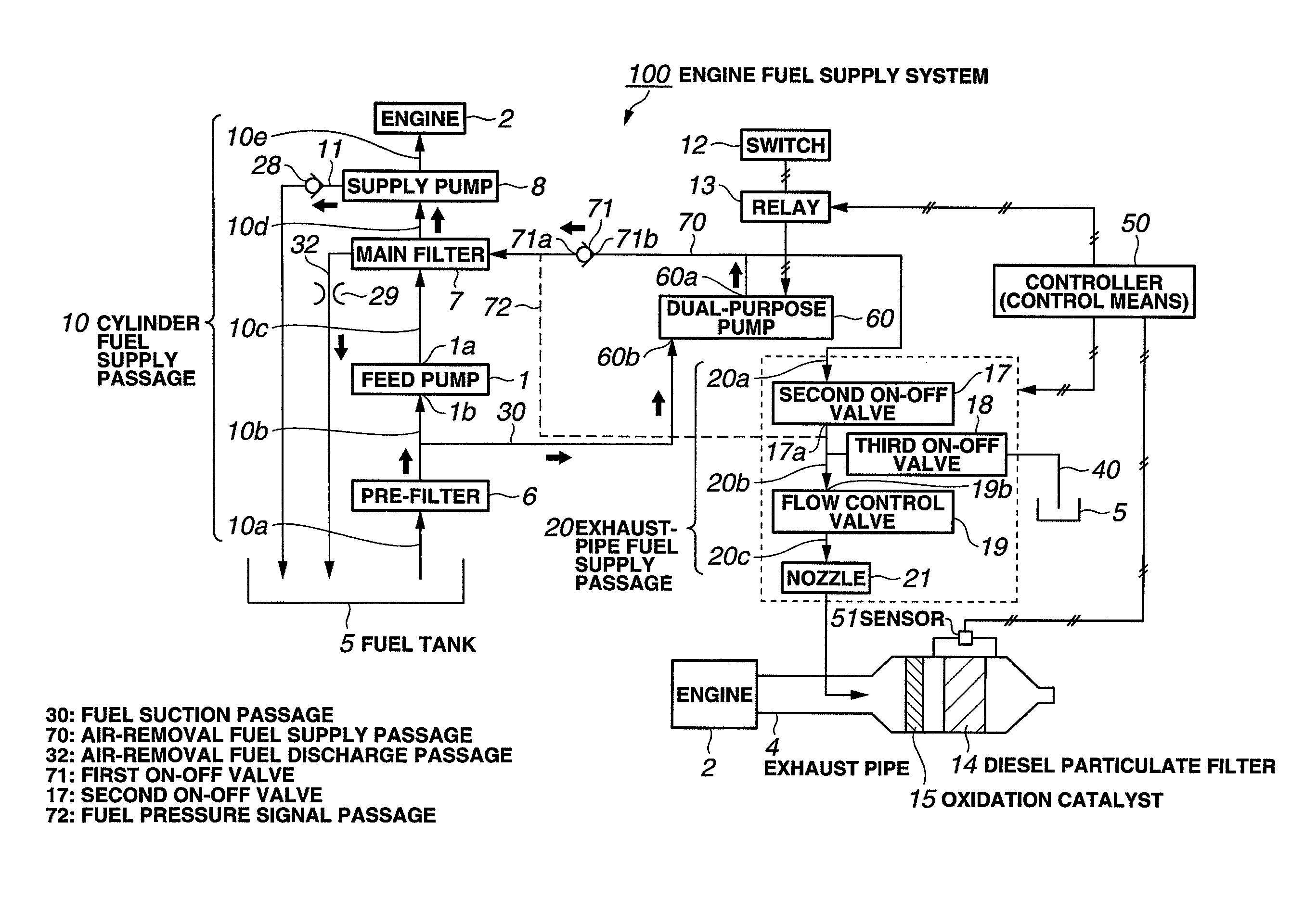
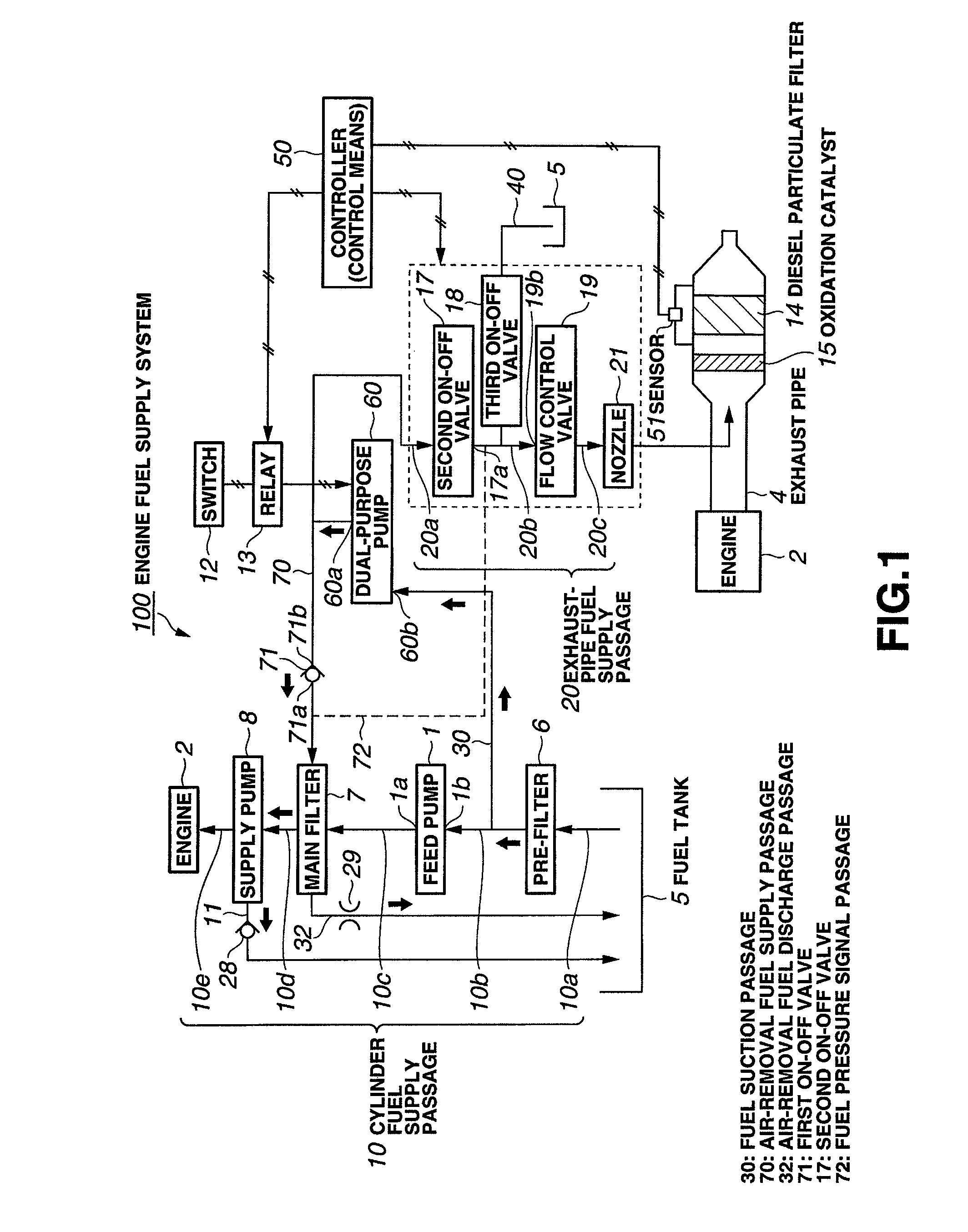
[0081]FIG. 1 is a configuration diagram of an engine fuel supply system 100 according to an exemplary embodiment.

[0082]As shown in FIG. 1, the engine fuel supply system 100 according to the embodiment includes a cylinder fuel supply passage 10 for supplying fuel into a cylinder of an engine 2 via a feed pump 1, and an exhaust-pipe fuel supply passage 20 for supplying fuel to an exhaust pipe 4 of the engine 2.

[0083]The cylinder fuel supply passage 10 communicates a fuel tank 5 with the inside of the cylinder of the engine 2. There are disposed, in the cylinder fuel supply passage 10, the fuel tank 5, a pre-filter 6, a feed pump 1, a main filter 7, a supply pump 8, and the engine 2. The engine 2 is a diesel engine.

[0084]The feed pump 1 and the supply pump 8 together form a fuel pump. The pre-filter 6 is a fuel filter including a water separa...


PUM


Abstract

An engine fuel supply system is provided at a reduced cost by using a HC dosing pump that supplies fuel into an exhaust pipe also as a pump for a cylinder fuel supply device. When a signal is generated to command air removal from a cylinder fuel supply passage, the dual-purpose pump is activated, a first on-off valve assumes an open state, and a second on-off valve assumes a close state, so that the fuel is supplied from the dual-purpose pump to the cylinder fuel supply passage via an air-removal fuel supply passage. When a signal is generated to command fuel supply into the exhaust pipe, the dual-purpose pump is activated, the second on-off valve assumes the open state, and the first on-off valve assumes the close state, so that the fuel is supplied from the dual-purpose pump to the exhaust pipe via the exhaust-pipe fuel supply passage.

Description

TECHNICAL FIELD[0001]This invention relates to an engine fuel supply system, and particularly to an engine fuel supply system which removes air from a cylinder fuel supply passage and supplies fuel into an exhaust pipe.BACKGROUND ART[0002]1. Related Conventional Arts[0003]FIGS. 10A and 10B show engine fuel supply systems 100 according to related conventional arts, respectively.[0004]FIG. 10A shows a cylinder fuel supply device 110 for supplying fuel into a cylinder of an engine 2 via a feed pump 1. FIG. 10B shows an HC (hydrocarbon) dosing device 120 for supplying fuel to an exhaust pipe 4 of an engine 2.[0005]In the cylinder fuel supply device 110 shown in FIG. 10A, fuel in a fuel tank 5 is sucked by the feed pump 1 via a supply passage 10a, a pre-filter 6, and a supply passage 10b. The feed pump 1 discharges the fuel to a supply passage 10c after raising the pressure of the fuel to a predetermined fuel pressure, for example to about 3 to 5 kgf / cm2. The fuel the pressure of which h...

Claims


Application Information

Patent Timeline
Patent Type & Authority Patents(United States)
IPC IPC(8): F02M23/00
CPCF01N3/0253F01N3/36F01N2610/03F01N2610/14F01N2610/1473F02M37/0047F02M37/18F02M37/20F01N13/0097
Inventor KAWASHIMA, YASUKUNIORITA, TETSUO
Owner KOMATSU LTD
Why Eureka
Try Eureka