
Apparatus for screeding concrete

Active Publication Date: 2012-04-10
LIGCHINE INT CORP
View PDF33 Cites 21 Cited by
  • Summary
  • Abstract
  • Description
  • Claims
  • Application Information

AI Technical Summary

Benefits of technology

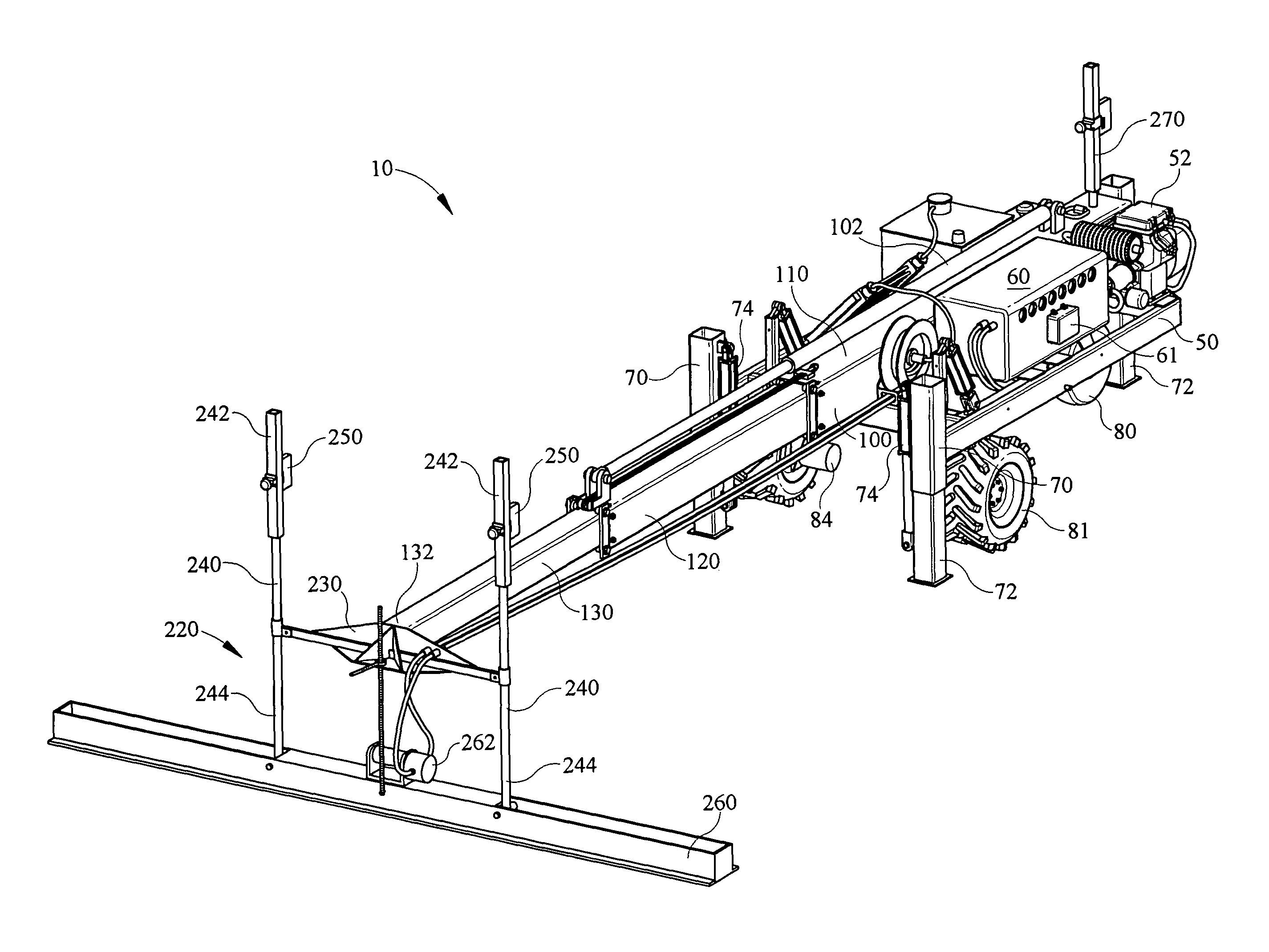
[0012]In one embodiment, the invention further comprises a telescopic boom assembly having an exterior, intermediate and interior boom, wherein the intermediate and interior booms may be extended and retracted by means of a single hydraulic cylinder. The exterior boom is secured directly to the frame assembly. Additionally, the boom assembly comprises a plurality of front and rear leveling plates which permits extremely accurate leveling of the interior and intermediate booms with respect to the exterior boom, and thus with respect to the frame of the screeding apparatus. This feature of the invention provides for an extremely level finished concrete surface at a fraction of the cost of more complex screeding systems.

Problems solved by technology

In large poured areas it is unwieldy and labor intensive to manually level and smooth a poured surface as well as extremely difficult to maintain a consistent finished grade.
These screeding systems are typically quite complex and costly due to the need for complicated mechanical and electrical controls not to mention the power required to position a turret.
In fact, while many prior art screeding devices are available, a great deal of concrete screeding is still accomplished by hand due to the size and cost of automated screeders.
Additionally, turret-type systems, while providing for consistently level finished surfaces are extremely complex in terms of mechanical construction and control systems required for operation since they necessarily have a boom that extends from a central point of attachment to the screeder.
Another disadvantage in prior art screeding systems is the inability to level the boom relative to the screed head and the frame or body of the system.
However, there remains a great deal of play or “slop” in the leveling process due to the size and weight of the boom and it's attachment to the screeder frame.

Method used


Image

  • Apparatus for screeding concrete
  • Apparatus for screeding concrete
  • Apparatus for screeding concrete

Examples


Embodiment Construction

)

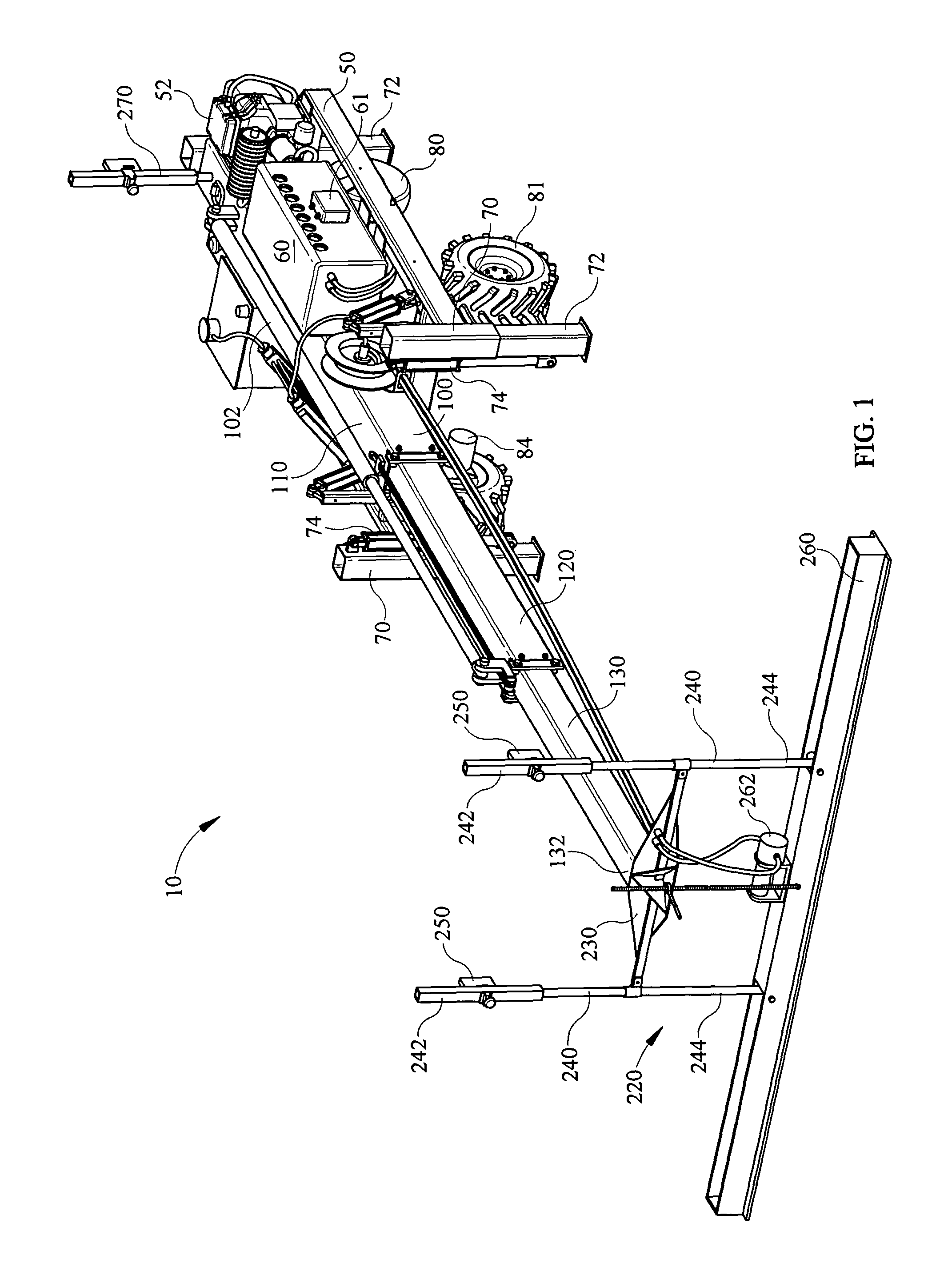
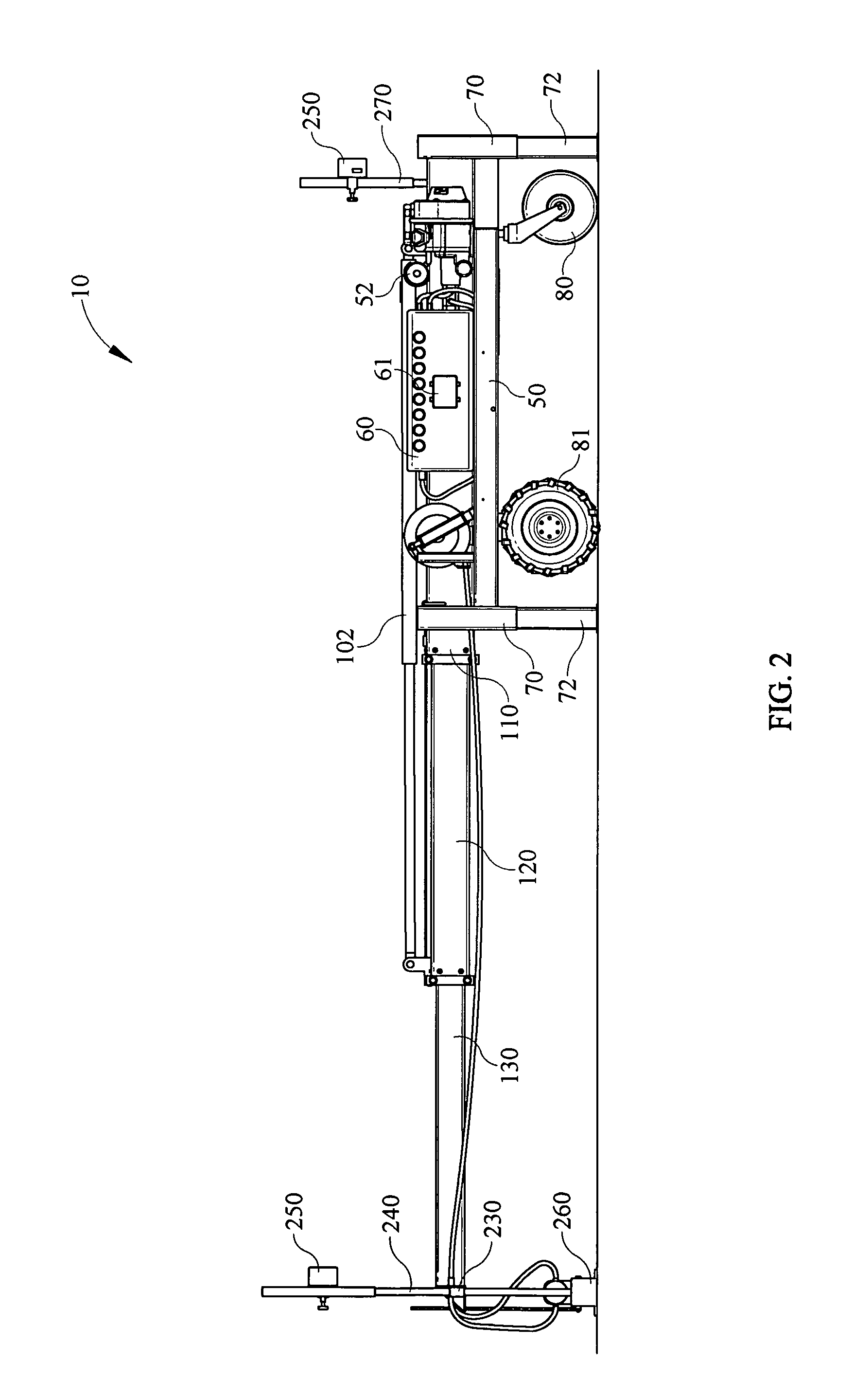
[0028]Referring now to FIGS. 1-4 and in accordance with one embodiment of the present invention, a concrete screeding apparatus 10 comprises a rigid frame assembly 50 on which a conventional internal combustion engine 52 is mounted. Engine 52 supplies power via a conventional output shaft to an hydraulic assembly 60, also mounted on frame assembly 50. Hydraulic assembly 60 may typically include a pump for pressurizing hydraulic fluid and a plurality of electrically actuated control values (not shown) for supplying pressurized hydraulic fluid to a plurality of components as discussed in detail below. Hydraulic assembly 60 may further comprise a control system (not shown) which may include a microprocessor, data memory, inputs and outputs, a wireless transceiver 61, and requisite wiring to electrically connect the control system to the plurality of valves. Throughout the specification the operation of hydraulic cylinders will be understood to be effected through the use of a conventi...


PUM


Abstract

An apparatus for screeding concrete to produce a level finished surface includes a rigid frame assembly; a telescopic boom assembly secured directly to the frame assembly; and a screeder head assembly having a plurality of vertically oriented alignment poles secured to the boom assembly. The telescopic boom assembly may include a plurality of boom sections, each having a leveling mechanism whereby each boom section may be individually leveled with respect to each preceding boom section to provide for a consistently level finished surface.

Description

BACKGROUND OF THE INVENTION[0001]1. Field of the Invention[0002]The present invention relates generally to a method and apparatus for troweling or screeding concrete and more specifically to an apparatus for screeding a poured concrete surface having a rigid frame structure and a telescopic boom that is secured directly thereto, said telescopic boom constructed to include a leveling system to maintain each section of the boom level with each preceding section thereof eliminating the need for continuous leveling controls, thereby providing a superior level finished surface.[0003]2. Description of the Related Art[0004]In the construction industry when liquid concrete is poured to produce a finished level surface it must be carefully leveled and smoothed, or screeded, so that when the concrete sets it produces an even, level surface. Since this level surface is almost always a foundation for additional construction, machine base applications, or for vertical storage such as warehousing...

Claims


Application Information

Patent Timeline
IPC IPC(8): E01C19/22
CPCE01C19/006E01C19/405E01C19/42
Inventor LIGMAN, PETER A.
Owner LIGCHINE INT CORP
Learn More