
Computer-assisted planning method for correcting changes in the shape of joint bones

a computer-aided planning and joint bone technology, applied in the field of computer-aided planning to correct changes in the shape of joint bones, can solve problems such as bone surface wear and bone interference in the joint region, and achieve the effect of easy output and volume of bon

Active Publication Date: 2012-04-10
SMITH & NEPHEW INC +2
View PDF7 Cites 18 Cited by
  • Summary
  • Abstract
  • Description
  • Claims
  • Application Information

AI Technical Summary

Benefits of technology

The invention provides a computer-assisted planning method for correcting changes in the shape of joint bones by identifying and measuring contour deviations of the joint bones in a data set, such as a computer tomography scan or a nuclear spin tomography scan. The method uses a three-dimensional imaging data set to determine the shape of the joint bones and the volume of material to be removed during a surgical procedure. The method can also include simulating the movement of the joint bone and identifying areas of interference between bones. The technical effects of the invention include improved accuracy in joint bone shaping and reduced damage to surrounding tissues during surgery.

Problems solved by technology

Bone anomalies can occur in the region of the pelvic joint and can lead to bone interferences in the joint region.
When the leg moves over time these interferences can cause bone surfaces to wear.

Method used


Image

  • Computer-assisted planning method for correcting changes in the shape of joint bones
  • Computer-assisted planning method for correcting changes in the shape of joint bones
  • Computer-assisted planning method for correcting changes in the shape of joint bones

Examples


Embodiment Construction

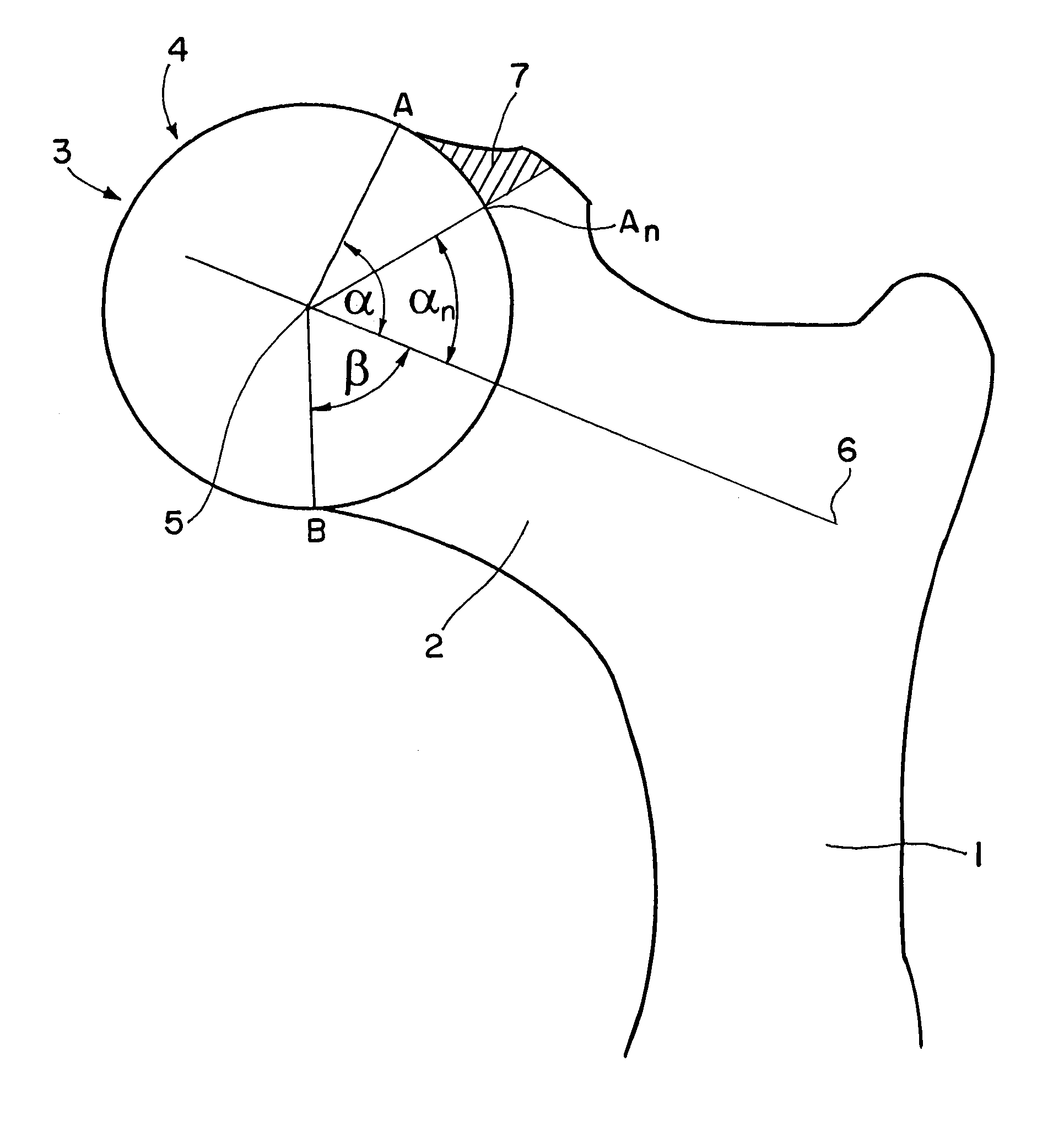
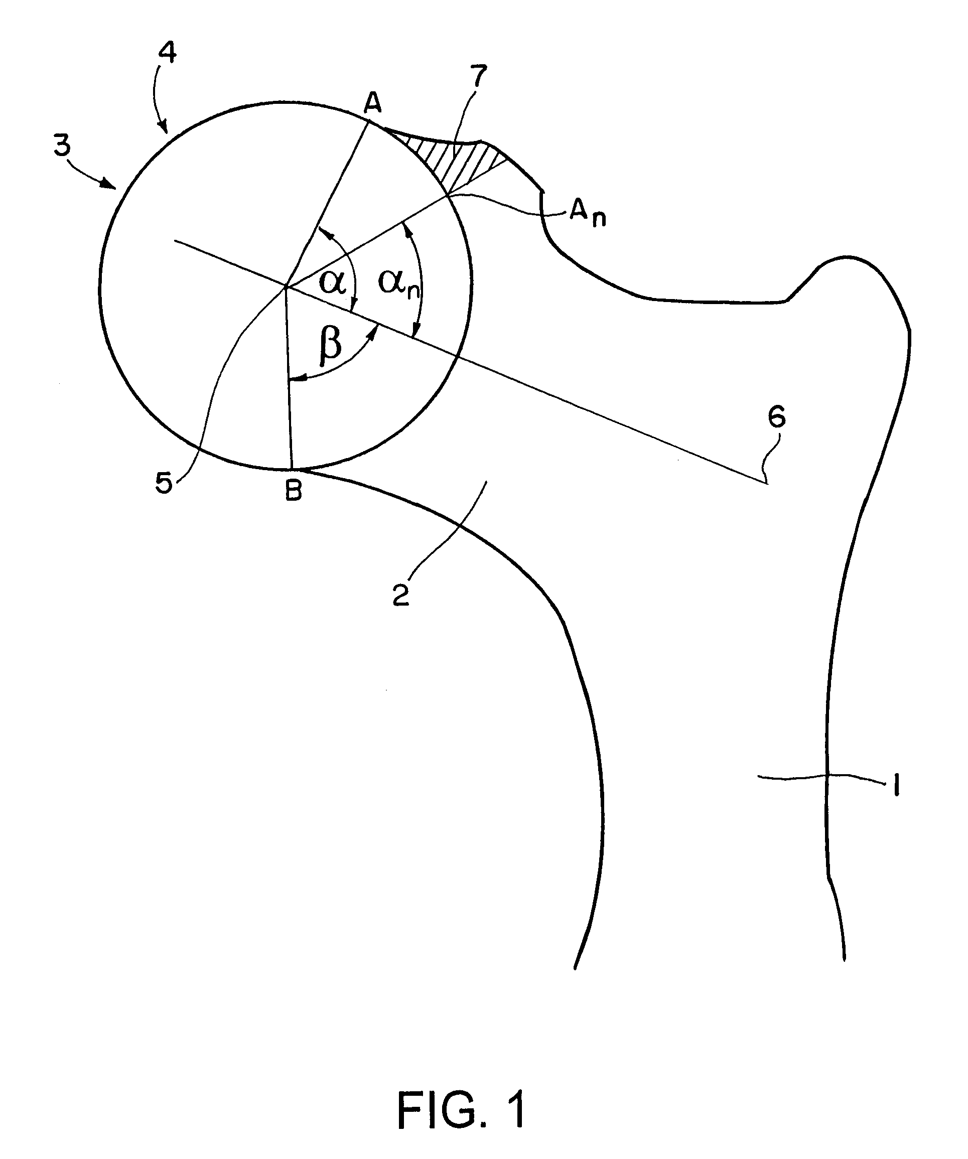
[0032]FIG. 1 shows the neck region of a femoral bone 1, comprising a femoral neck 2 and a joint head 3. The joint head 3 has been inscribed with a sphere 4 that is shown as a circle in the sectional representation in FIG. 1. A center point 5 of the sphere 4 simultaneously forms the center point of the joint head 3 (head of the femur). Also shown in FIG. 1 are a femoral neck axis 6, and a protruding volume of bone shown as crosshatched region 7 (also known as a deviating volume), that can cause interference in the hip joint and arthritis.

[0033]To determine the deviating volume 7, particular angles are used as indicated in FIG. 1 as arcs in the circle having the center point 5. In a preoperative situation, an angle α indicates the angle between the neck axis 6 and a line 5-A, wherein A is the first point on the sphere at which the contour of the bone deviates from a spherical shape. An angle β is the angle between the neck axis 6 and a line 5-B on the lower (“healthy”) side of the fem...


PUM


Abstract

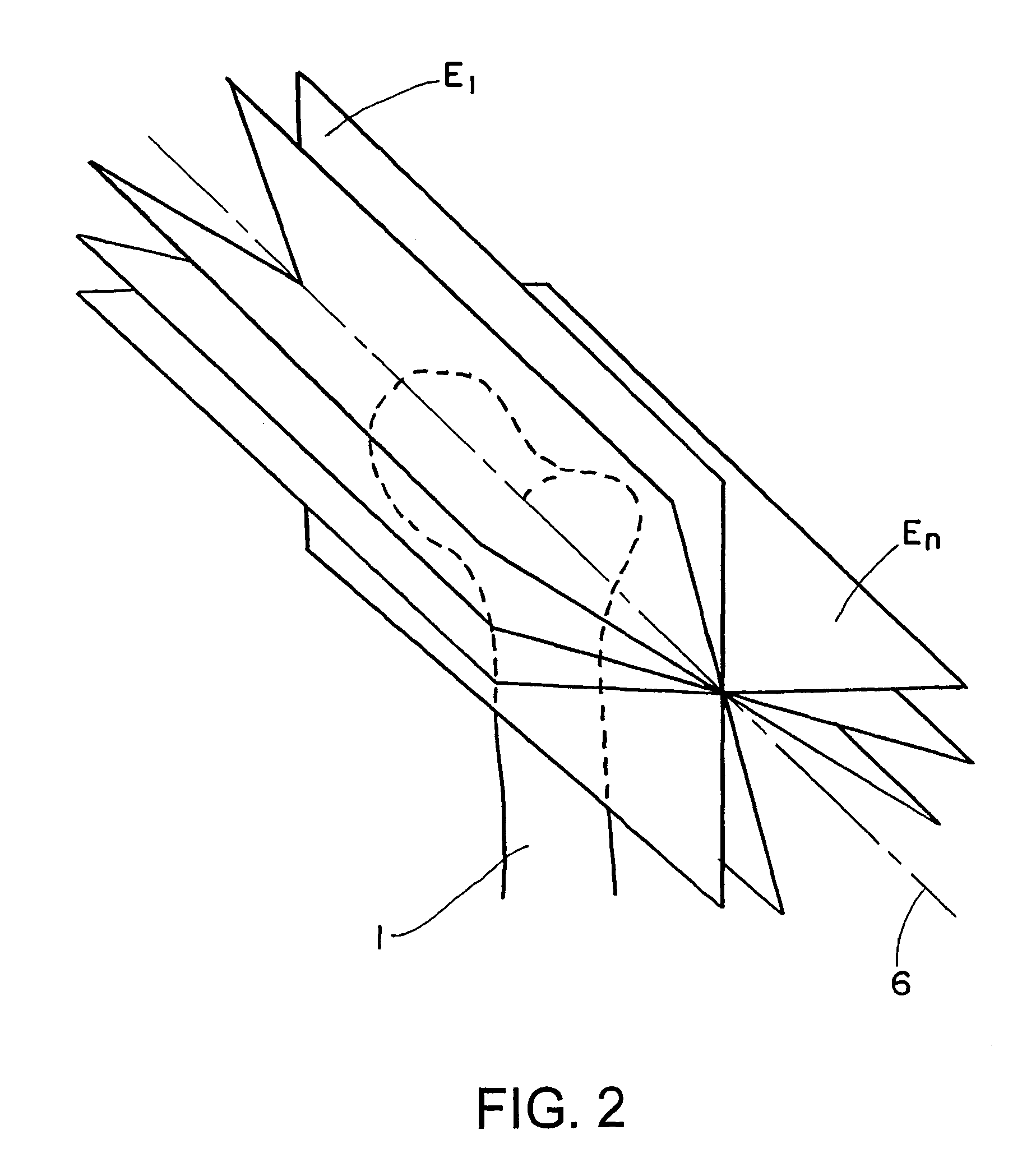
The patent discloses a system and method for correcting changes in the shape of joint bones in a bone joint, including: providing a three-dimensional imaging data set of a bone joint; identifying the joint bones in the data set based on the shapes of the joint bones; inscribing a portion of a joint bone to be reconstructed with a base shape; determining contour deviations of the inscribed joint bone from the base shape by ascertaining contour distances between the base shape and the shape of the inscribed joint bone in different incision planes; determining a three-dimensional deviating volume using the contour deviations; and using the deviating volume for correction planning.

Description

RELATED APPLICATION DATA[0001]This application claims priority of U.S. Provisional Application No. 60 / 951,281 filed on Jul. 23, 2007, and EP 07110358 filed on Jun. 15, 2007, which are incorporated herein by reference in their entirety.FIELD OF THE INVENTION[0002]The invention relates to a system and method for computer-assisted planning to correct changes in the shape of joint bones.BACKGROUND OF THE INVENTION[0003]Changes in the shape of joint bones are a possible cause of arthritic joint diseases. Bone anomalies can occur in the region of the pelvic joint and can lead to bone interferences in the joint region. When the leg moves over time these interferences can cause bone surfaces to wear. Computer-assisted planning can be used to prepare reconstruction treatments that restore a suitable bone shape. Computer-assisted planning has been based on determining the contour of joint bones on a two-dimensional basis (for example, in a particular incision plane). The reference “Journal of...

Claims


Application Information

Patent Timeline
Patent Type & Authority Patents(United States)
IPC IPC(8): A61B5/103
CPCA61B19/52A61B19/50A61B2019/5289A61B34/10A61B90/36A61B2090/364
Inventor TUMA, GREGORSCHINDLER, FLORIANFRICKE, MARCHAIMERL, MARTIN
Owner SMITH & NEPHEW INC
Learn More