
Method and apparatus for measuring the thickness of a metal layer provided on a metal object

a metal object and thickness technology, applied in the direction of magnetic measurement, electric/magnetic measuring arrangement, instruments, etc., to achieve the effect of easy detection

Active Publication Date: 2012-04-10
ABB (SCHWEIZ) AG
View PDF5 Cites 1 Cited by
  • Summary
  • Abstract
  • Description
  • Claims
  • Application Information

AI Technical Summary

Benefits of technology

[0010]The invention makes it possible to automatically determine the thickness of a metal layer on a metal object. Further, the invention makes it possible to determine the thickness of the layer without being in contact with the layer or the object. Thus, the method according to the invention is suitable for use in the production of products including a metal layer provided on a metal sheet or strip, such as for thickness control of the layer.
[0011]Although it is possible to use different types of variations of the magnetic field, it is suitable to generate the variation as a step function in which the magnetic field is suddenly changed to a value that considerably differs from its previous value. The magnetic field can be dropped to a considerably lower value, or the magnetic field can be increased to a considerably higher value. For example, the variation is generated by suddenly allowing the magnetic field to drop to zero. Such a step function is easy to generate and facilitates the calculation of the thickness of the layer.
[0014]According to an embodiment of the invention, the method comprises integrating the measured changes of the magnetic field, and determining the thickness of the layer based on a mathematical relation between the thickness of the layer and the integral of the measured values of the changes of the magnetic field. This embodiment utilizes the fact that the depth of penetration is proportional to the integral of the measured change of the magnetic field. Integrating the measured values is advantageous since it provides stable measuring values and facilitates the understanding of the measuring.
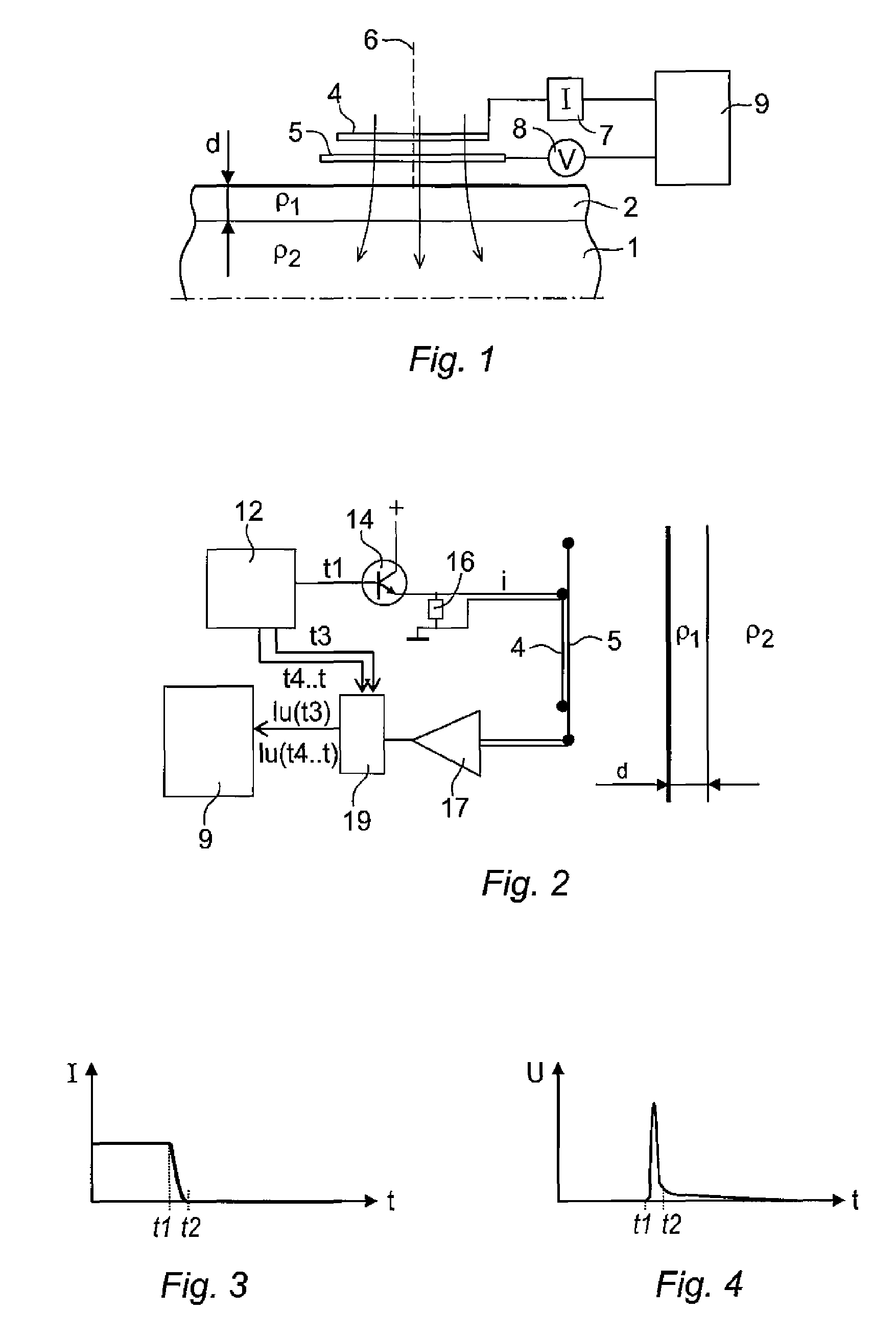
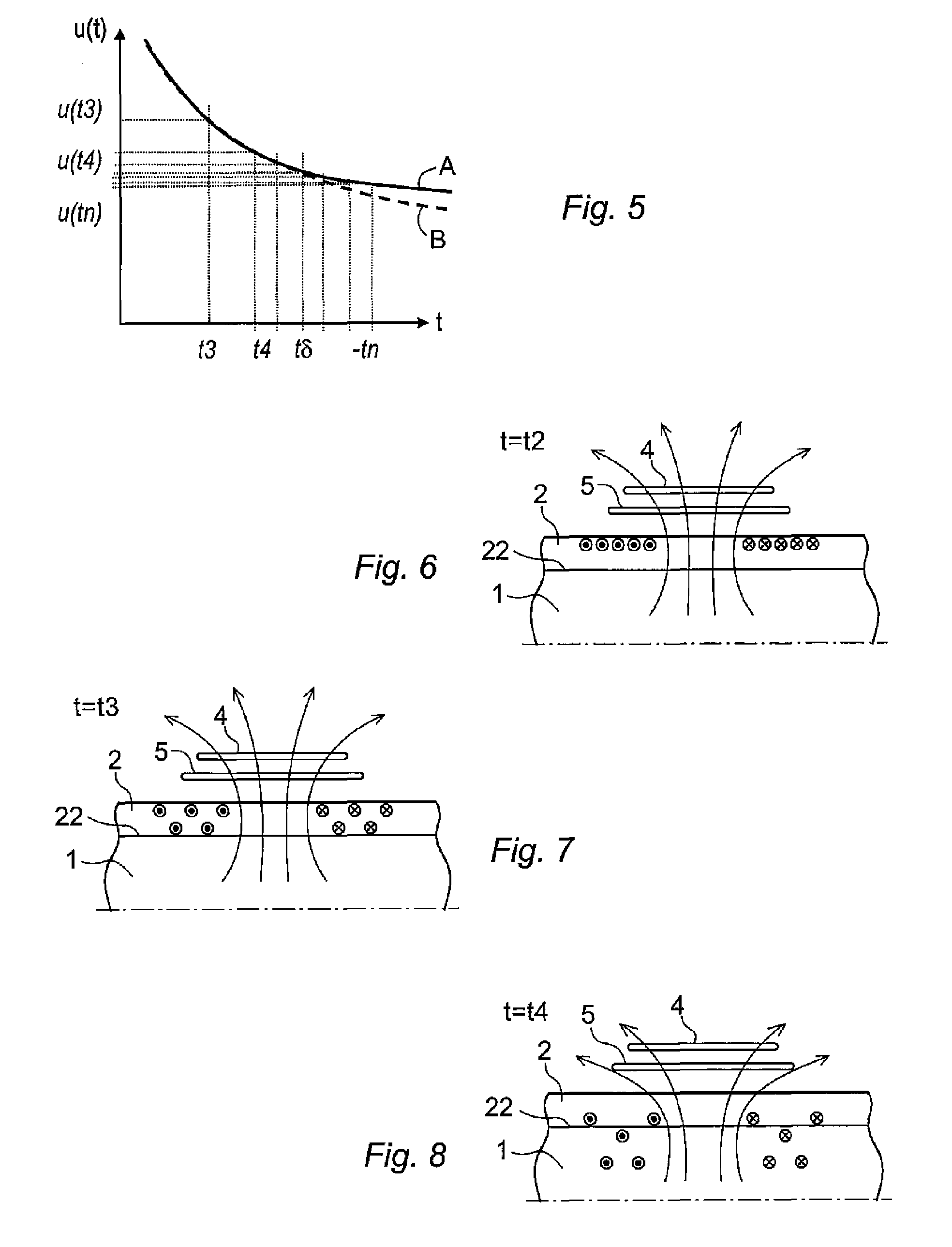
[0017]After some time when the induced current has propagated a portion into the material of the object, an essentially straight line is obtained again, but with a different slope. The slope of this line is proportional to the resistivity of the material of the object. Accordingly, there is a detectable change in the integral of the measured voltage, i.e. in the change of the magnetic field, at the point in time when the current passes the boundary between the layer and the object. This change makes it possible to determine the integral of the measured change of the magnetic field at the point in time when the current passes the boundary between the metal layer and the object. The thickness of the layer is calculated based on the integral of the measured change of the magnetic field at the point in time when the current passes the boundary between the metal layer and the metal object and a predetermined constant.
[0018]According to an embodiment of the invention, the method comprises determining the point in time when the relation between the integral of the measured change of the magnetic field and the square root of the time deviates from linearity, which is the point in time when the current passes the boundary, and based thereon determining the integral of the measured change of the magnetic field at the point in time when the current passes the boundary. According to this embodiment it is detected when the measured values of the changes of the magnetic field deviates from expected values of changes of a magnetic field for a homogeneous object by detecting when the relation between the integral of the measured change of the magnetic field and the square root of the time deviates from linearity. An advantage with this embodiment is that it is easy to detect when the measured values deviate from linearity.
[0021]According to an embodiment of the invention, the method comprises determining the resistivity of the metal layer based on the measured changes of the magnetic field before the variation of the magnetic field has propagated through the metal layer. In some applications there is a desire to determine the resistivity of the layer and / or the resistivity of the object. According to an embodiment of the invention, the method comprises determining the resistivity of the metal object based on the measured change of the magnetic field after the variation of the magnetic field has propagated through the metal layer. Due to the fact that the measured voltage is proportional to the square root of the resistivity, it is possible to determine the resistivity of the layer and the object using the same measurement values that are used for determining the thickness of the layer. Further, it is an advantage to determine the resistivity of the layer and the object and use the determined resistivity to facilitate the calculations of the thickness of the layer.

Problems solved by technology

A problem with this production method is that the different metal sheets may have different floating properties during deformation and accordingly the sheets are differently compressed during the rolling.

Method used


Image

  • Method and apparatus for measuring the thickness of a metal layer provided on a metal object
  • Method and apparatus for measuring the thickness of a metal layer provided on a metal object
  • Method and apparatus for measuring the thickness of a metal layer provided on a metal object

Examples


Embodiment Construction

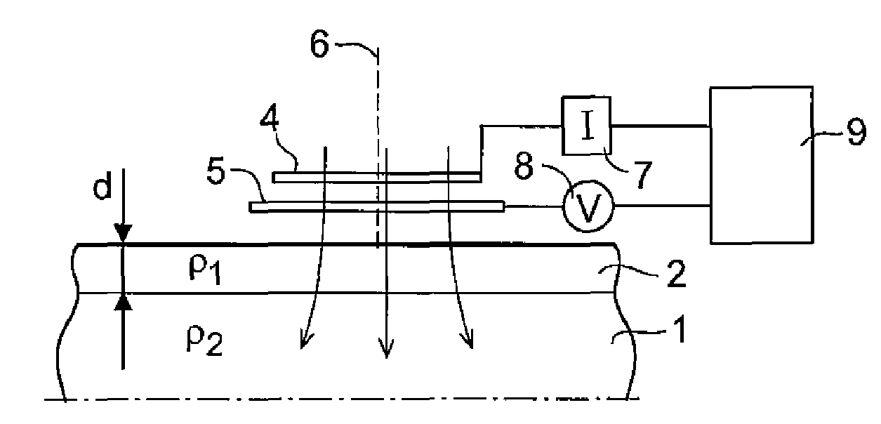
[0036]FIG. 1 shows and apparatus for measuring the thickness of a metal layer 2 on a metal object 1 according to an embodiment of the invention. The object 1 is made of metal or a metal alloy and is provided with a layer 2 of a metal or a metal alloy having a resistivity that differs from the resistivity of the object. The layer is thin compared with the thickness of the object. The layer is, for example, between 0.1 mm and 1 mm. The object 1 is, for example, a sheet and the layer can be provided on one side or both sides of the sheet. The thickness d of the layer 2 is to be measured.

[0037]The apparatus comprises a first device arranged to generate a magnetic field and positioned close to the metal layer. The first device includes a coil 4, in the following called a sending coil, and current supply means 7 for supplying a current to the sending coil 4. The first device is arranged to generate a magnetic field and a sudden variation of the magnetic field so that a current is induced ...


PUM


Abstract

A method and an apparatus for measuring the thickness of a metal layer. The metal layer has a resistivity (ρ1) that differs from the resistivity (ρ2) of the metal object. The apparatus includes a first device arranged to generate a magnetic field in close vicinity of the metal layer, and to generate a variation of the magnetic field so that a current is induced in the surface of the metal layer, a second device arranged to measure the changes of the magnetic field outside the metal layer due to the induced current during a time period that is longer than the time it takes for the current to propagate through the metal layer, and a computing unit to determine the thickness of the layer based on a mathematical relation between the thickness of the layer and the measured values of the changes of the magnetic field.

Description

CROSS-REFERENCE TO RELATED APPLICATIONS[0001]The present application is a continuation of pending International patent application PCT / EP2009 / 053140 filed on Mar. 17, 2009 which designates the United States and the content of which is incorporated herein by reference.FIELD OF THE INVENTION[0002]The present invention relates to a method and an apparatus for measuring the thickness of a metal layer provided on a metal object, such as a metal sheet or a metal strip. The invention is, for example, suitable for measuring the thickness of metal layers and metal objects made of different types of aluminum alloys.BACKGROUND OF THE INVENTION[0003]Today, in the production of metal objects, such as a metal sheets and metal strips, it is common to produce objects having a plurality of layers of different metals or metal alloys. An object of a metal alloy can, for example, be protected with a thin film or a layer of another alloy than the object. For example, an aluminum sheet of a certain alloy...

Claims


Application Information

Patent Timeline
Patent Type & Authority Patents(United States)
IPC IPC(8): G01B7/06
CPCG01B7/105
Inventor LINDER, STENTHEGEL, LENNART
Owner ABB (SCHWEIZ) AG
Learn More