Interframe prediction processor with mechanism for providing locations of reference motion vectors used in macroblock adaptive field/frame mode

a technology of macroblock adaptive field and prediction processor, which is applied in the direction of signal generator with optical-mechanical scanning, color television with bandwidth reduction, etc., can solve the problems of degrading the efficiency of video coders and decoders, and achieve the effect of high speed

Inactive Publication Date: 2012-04-10
SOCIONEXT INC
View PDF16 Cites 20 Cited by
  • Summary
  • Abstract
  • Description
  • Claims
  • Application Information

AI Technical Summary

Benefits of technology

[0015]In view of the foregoing, it is an object of the present invention to provide a device that performs interframe prediction at a high speed for video signal coding and decoding. It is also an object of the present invention to provide video coding and video decoding devices employing the proposed interframe prediction device.

Problems solved by technology

This conversion task imposes an additional processing burden, thus degrading the efficiency of video coders and decoders.

Method used


Image

  • Interframe prediction processor with mechanism for providing locations of reference motion vectors used in macroblock adaptive field/frame mode
  • Interframe prediction processor with mechanism for providing locations of reference motion vectors used in macroblock adaptive field/frame mode
  • Interframe prediction processor with mechanism for providing locations of reference motion vectors used in macroblock adaptive field/frame mode

Examples


first embodiment

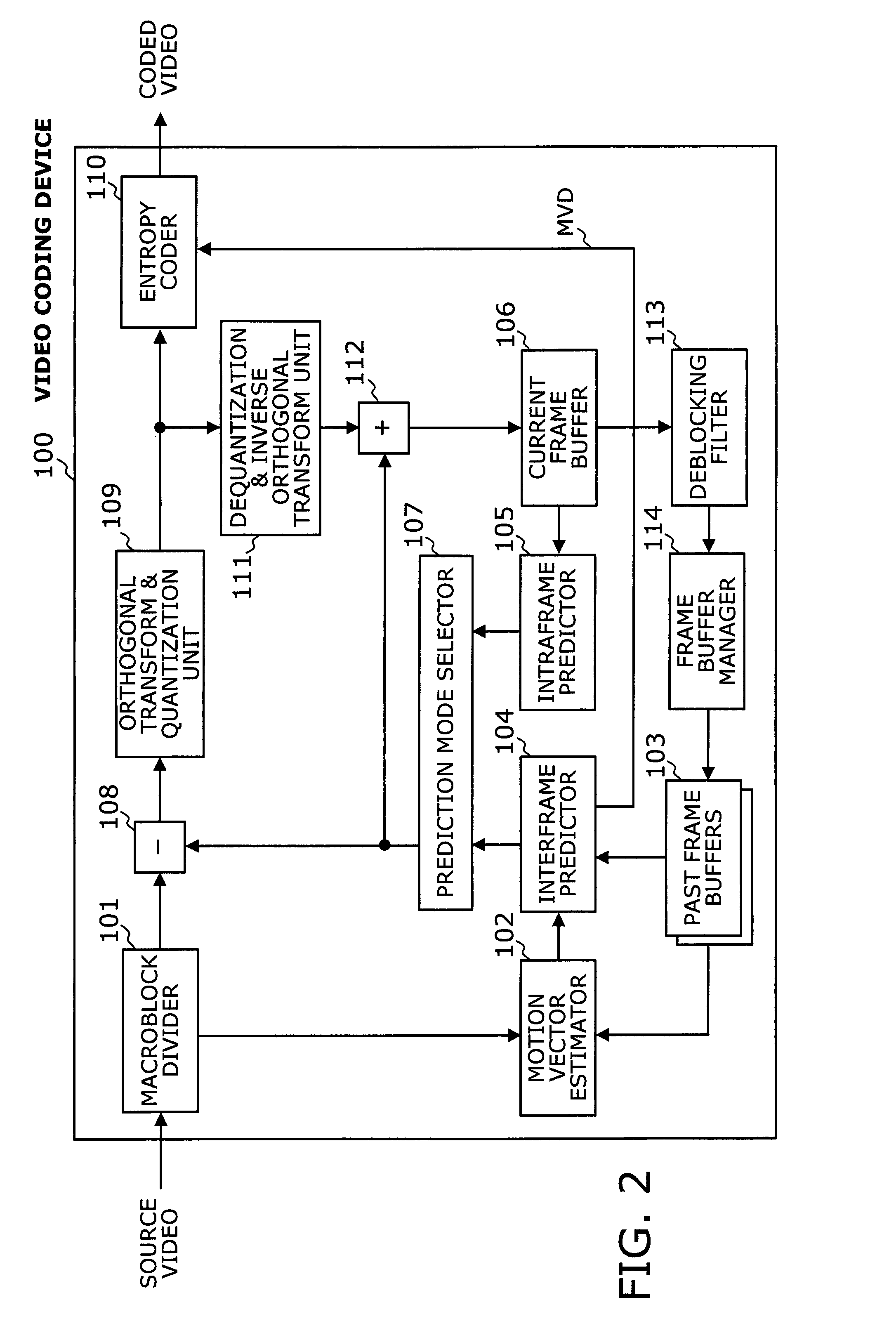
[0061]FIG. 3 is a block diagram of a video decoding device according to the first embodiment of the present invention. The illustrated video decoding device 200 is formed from the following elements: an entropy decoder 201, a dequantization & inverse orthogonal transform unit 202, an adder 203, a current frame buffer 204, an intraframe predictor 205, a prediction mode selector 206, a deblocking filter 207, a frame buffer manager 208, past frame buffers 209, and an interframe predictor 210. With those elements, the video decoding device 200 decodes a coded video signal produced by the video coding device 100 of FIG. 2.

[0062]A given coded video signal is entropy-decoded by the entropy decoder 201 and then dequantized and back-transformed by the dequantization & inverse orthogonal transform unit 202. The outcomes of this decoding process include, among others, coding mode parameters and, in the case of interframe coding, motion vector data in the form of MVD. Based on the decoded codin...

second embodiment

[0153]This and subsequent sections describe a video decoding device according to a second embodiment of the present invention and, more particularly, how its interframe predictor decodes motion vectors. The second embodiment is different from the first embodiment in its capability of MBAFF processing. The following description will focus on this difference, using the same reference numerals as in the first embodiment to refer to like elements in the second embodiment.

[0154]In MBAFF mode, the term “current macroblock pair” is used to refer to a pair of 16×16 macroblocks that are currently processed, while two macroblocks adjacent to the current macroblock pair are called an “adjacent macroblock pair.” In the following description of the second embodiment, the suffixes “a” and “b” are attached to reference numerals of the top macroblock and bottom macroblock belonging to a specific macroblock pair. According to the second embodiment, the MVP calculator 212 stores motion vectors of a c...


PUM


Abstract

An interframe prediction processor designed for high-speed video coding and decoding. The interframe prediction processor has an address selector and a predictor calculator. The address selector receives information about MBAFF type and coding type. When performing motion compensation for a given MBAFF picture with reference to blocks surrounding a current block, the address selector provides memory addresses of reference motion vectors according to the coding type of the current block pair, as well as to the coding type of the reference blocks. The predictor calculator that determines a motion vector predictor for each constituent block of the current block pair based on reference motion vectors read out of the provided memory addresses.

Description

CROSS-REFERENCE TO RELATED APPLICATIONS[0001]This application is based upon and claims the benefits of priority from the prior Japanese Patent Application No. 2006-223564, filed on Aug. 18, 2006, the entire contents of which are incorporated herein by reference.BACKGROUND OF THE INVENTION[0002]1. Field of the Invention[0003]The present invention relates to a device for predicting a frame from other frames, as well as to video coding and decoding devices using the same. More particularly, the present invention relates to an interframe prediction processor, a video coding device, and a video decoding device that perform interframe prediction of video frames on a block basis.[0004]2. Description of the Related Art[0005]Digital video compression techniques are widely used in many applications. MPEG and H.264 are among the standard specifications in this technical field, where MPEG stands for “Moving Picture Expert Group.” The coding and decoding algorithms used in those standards divide...

Claims


Application Information

Patent Timeline
Patent Type & Authority Patents(United States)
IPC IPC(8): H04N11/02H04N19/50H04N19/423H04N19/503H04N19/51H04N19/85
CPCH04N19/176H04N19/51H04N19/43H04N19/109H04N19/61
Inventor NAKAISHI, HIDENORI
Owner SOCIONEXT INC
Why Eureka
Try Eureka