Method for coupling light into a thin planar waveguide

a planar waveguide and light technology, applied in the direction of planar/plate-like light guides, lighting and heating apparatus, instruments, etc., can solve the problems of significant alignment problems and loss of optical power, and achieve the effect of facilitating alignment of light sources, good coupling efficiency, and good efficiency of optical power coupling

Active Publication Date: 2012-04-10
NOKIA TECH OY
View PDF1 Cites 112 Cited by
  • Summary
  • Abstract
  • Description
  • Claims
  • Application Information

AI Technical Summary

Benefits of technology

[0017]In an embodiment, a good efficiency of coupling the optical power of a light beam into a thin planar waveguide may be attained, although the thickness of the planar waveguide may be substantially smaller than the vertical dimension of the in-coupled light beam. The coupling efficiency may be improved especially when compared with the directly edge coupled arrangement of FIG. 1.
[0018]In an embodiment, the ridge of the light distributing device facilitates alignment of the light source when the vertical dimension of the in-coupled light beam is smaller than the height of the ridge. Thus, sensitivity to manufacturing tolerances may be reduced especially when compared with the directly edge coupled arrangement of FIG. 2.
[0019]In an embodiment, the ridge of the light distributing device may facilitate providing a more uniform distribution of optical intensity inside the planar waveguide than what can be attained by the directly edge-coupled arrangements, when using the same number of light sources.
[0021]In an embodiment, the improvement in the coupling efficiency, tolerance to misalignment, and a more uniform distribution of intensity in the planar waveguide may be attained simultaneously.

Problems solved by technology

Referring to FIG. 2, optical power may be also lost when the light source is misaligned with respect to the edge of a thin planar waveguide 10.
As the thickness of the planar waveguide may be e.g. 0.2 mm, and the manufacturing tolerances may be e.g. 0.5 mm, the alignment problem may be significant in mass production.

Method used


Image

  • Method for coupling light into a thin planar waveguide
  • Method for coupling light into a thin planar waveguide
  • Method for coupling light into a thin planar waveguide

Examples


Embodiment Construction

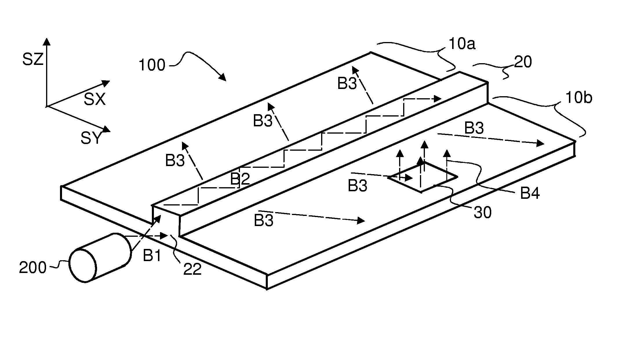
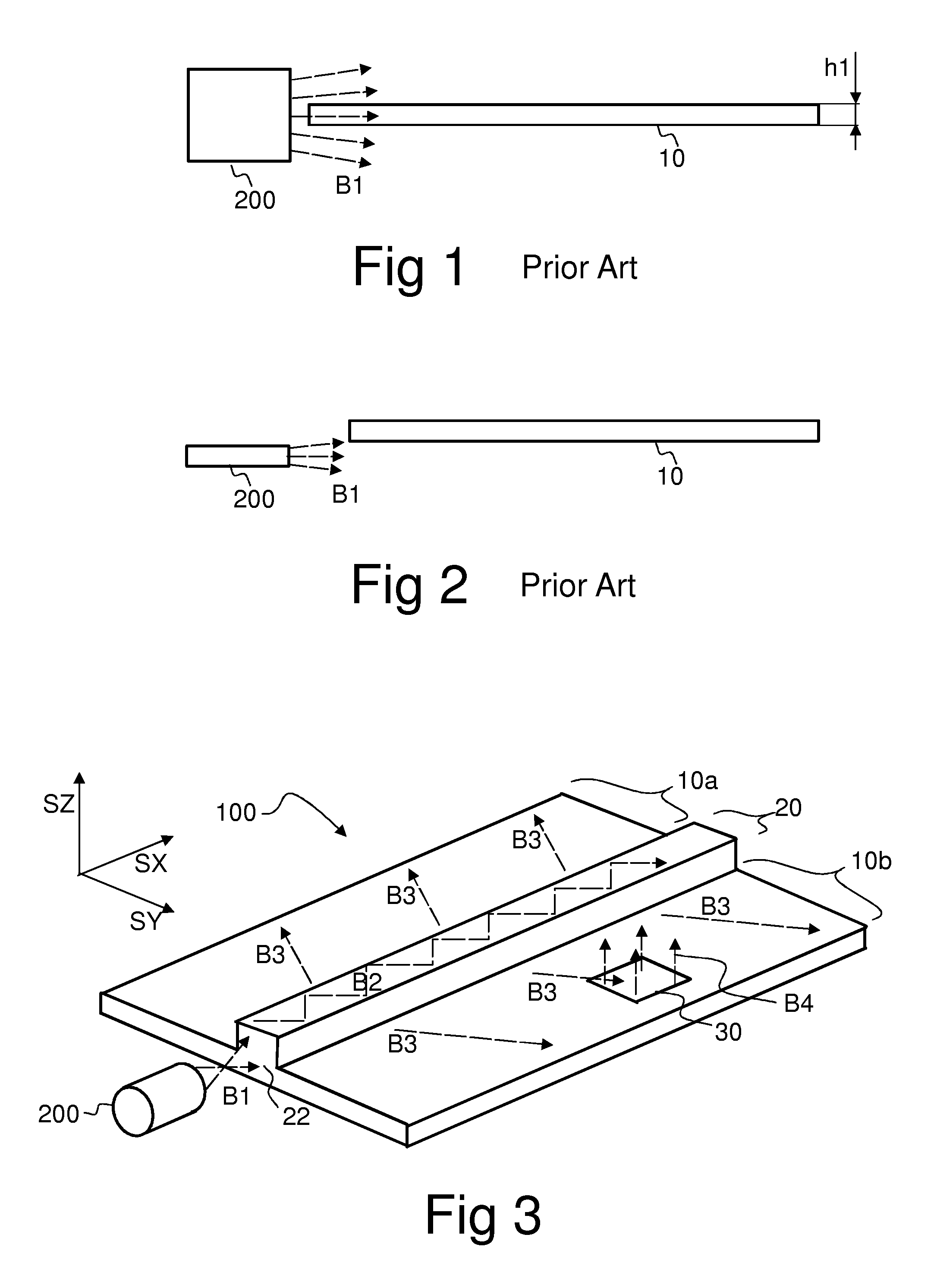
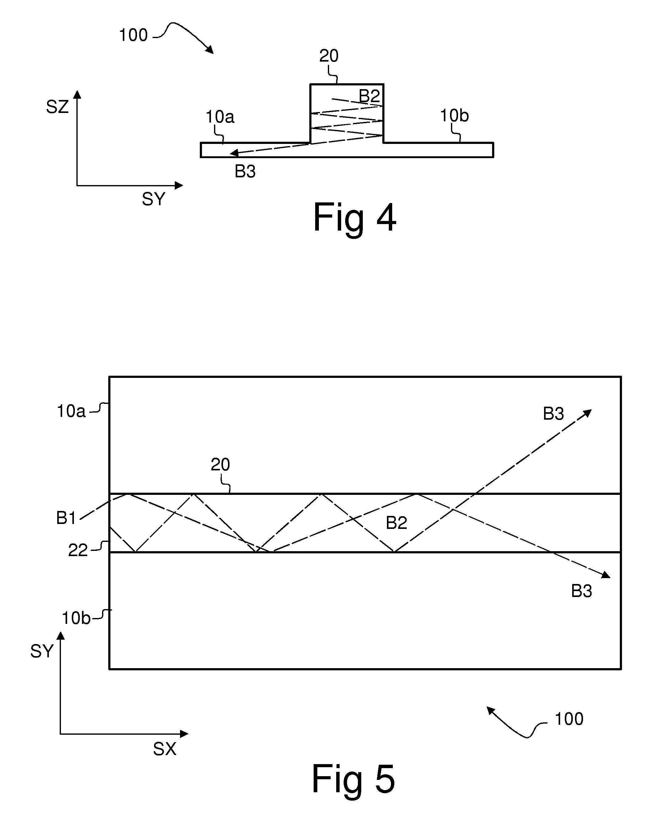
[0064]FIG. 3 shows a light distributing device 100 comprising planar waveguides 10a, 10b, and a ridge 20 to couple light into the planar waveguides 10a, 10b. A light beam B1 provided by a light source 200 is coupled into an end 22 of the ridge 20 in order to form a light beam B2 which propagates in the longitudinal direction SX of ridge 20.

[0065]The lower sides of the ridge 20 are optically coupled to the planar waveguides 10a, 10b. Thus, a fraction of the light B2 propagating in the ridge 20 is transversely coupled from the sides of the ridge 20 into the planar waveguides 10a, 10b, in order to form light B3 which propagates in the planar waveguides 10a, 10b.

[0066]The light is confined to the ridge 20 and to the planar waveguides 10a, 10b by total internal reflections, i.e. the light is waveguided in the ridge 20 and the planar waveguides 10a, 10b.

[0067]The light distributing device 100 may further comprise one or more out-coupling portions 30 to couple light out of the plane of t...


PUM


Abstract

A light distributing device (100) comprises a thin planar waveguide (10) and a waveguiding ridge (20). An incoming light beam (B1) coupled into the ridge (20) forms a second light beam (B2) waveguided in the ridge (20). The ridge (20) and the planar waveguide (10) have a common portion (23) such that light is further coupled from the side of the ridge (20) into the planar waveguide (10) through said common portion (23). Thus, optical power of a broad incoming beam (B1) may be effectively coupled to a relatively thin planar waveguide (10). The planar waveguide (10) may further comprise diffractive out-coupling elements (30) to direct light towards a display (400).

Description

RELATED APPLICATION[0001]This application was originally filed as and claims priority to PCT Application No. PCT / FI2006 / 050476 which was filed on Nov. 2, 2006.FIELD OF THE INVENTION[0002]The present invention relates to coupling light into planar waveguides.BACKGROUND OF THE INVENTION[0003]Planar waveguides are cost-effective devices to provide lighting for e.g. liquid crystal displays or keysets. Light which is initially provided e.g. by an external light emitting diode (LED) may be distributed to a larger area by means of a planar waveguide. The use of thin planar waveguides may facilitate reducing size, weight and manufacturing costs of a portable device.[0004]Referring to FIG. 1, optical power may be lost when a broad light beam B1 emitted by a light source 200 impinges on the edge of a thin planar waveguide 10, as the beam B1 overlaps only partially with the edge.[0005]Referring to FIG. 2, optical power may be also lost when the light source is misaligned with respect to the ed...

Claims


Application Information

Patent Timeline
Patent Type & Authority Patents(United States)
IPC IPC(8): G02B6/30
CPCG02B6/0028G02B6/0036H04M1/22G02B6/006
Inventor SAARIKKO, PASI RISTO OLAVILEVOLA, TAPANI KALERVOLAITINEN, PAULI
Owner NOKIA TECH OY
Why Eureka
Try Eureka