Robot control apparatus

a robot control and control device technology, applied in the direction of electric programme control, program control, instruments, etc., can solve the problems of difficult to accurately estimate the friction coefficient, the operation direction of the joint shaft of the joint shaft changes frequently and complicatedly, and the accuracy of estimating the external force is high. , to achieve the effect of stable force control

Active Publication Date: 2012-04-10
KK TOSHIBA
View PDF7 Cites 26 Cited by
  • Summary
  • Abstract
  • Description
  • Claims
  • Application Information

AI Technical Summary

Benefits of technology

[0008]A robot control apparatus and a robot control method according to the present invention have the advantage that it is possible to estimate an external force more highly accuracy and provide stable force control without using a force sensor.

Problems solved by technology

However, since the force sensor is fragile against impact as well as is expensive, it is frequent that use of the force sensor is avoided.
However, though it is necessary to highly accurately estimate parameters of a dynamics model in advance in order to estimate the drive torque, realization of such parameter estimation involves difficulty.
Accordingly, it is difficult to estimate the friction coefficient precisely.
In the motion of the actuator in the task coordinate system, an operation direction of a joint shaft thereof changes frequently and complicatedly.
As described above, in the case where the force sensor is not used in the external force estimation, it has been difficult to estimate the external force more highly accurately, and to provide stable force control.

Method used


Image

  • Robot control apparatus
  • Robot control apparatus
  • Robot control apparatus

Examples


first modification

[0087](First Modification)

[0088]As a first modification example of the embodiment of the present invention, a description will be made of a method of changing the parameter (gain) of the compliance model. For each joint of the robot, a magnitude of the friction torque differs owing to a difference in specifications of the velocity reducer, and the like. Accordingly, in the case where the compliance model is not provided, hardness (magnitude of minute displacement) against the external force at the tip end is not isotropic in an axial direction of the task coordinate system. Therefore, a difference in the threshold value of the dead band, which is set for each joint shaft, that is, a difference in the minimum external torque

[Math. 49]

τ,

is allowed to reflect on the parameter, whereby estimation accuracy of the external force is further enhanced. The external torque and the external force in the task coordinate system have a relationship shown in Expression (4). Accordingly, the correc...

second modification

[0092](Second Modification)

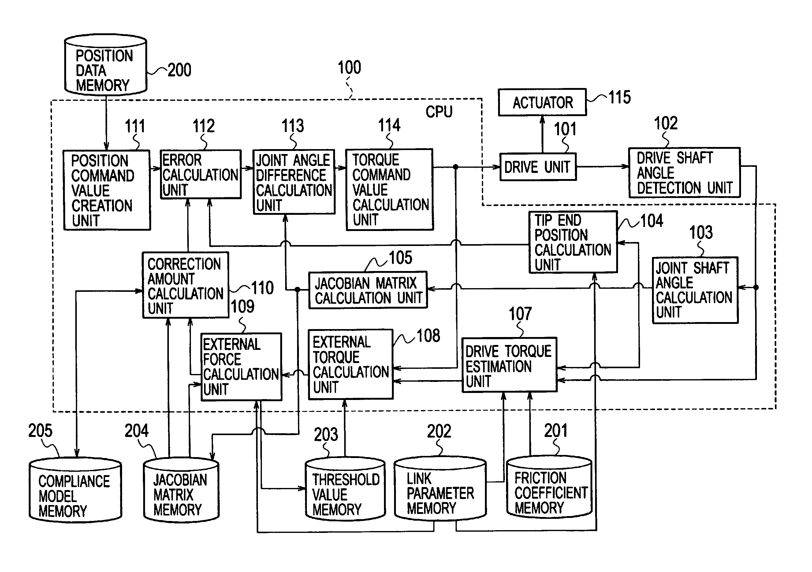
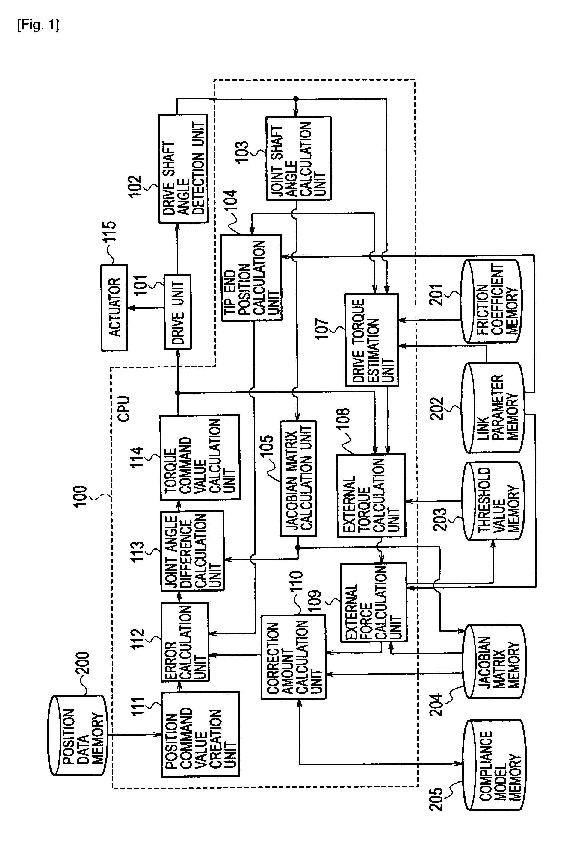
[0093]As a second modification example of the embodiment of the present invention, a description will be made of the case of using an inverse transform capable of directly calculating the joint angle from the tip end position without using the Jacobian matrix as in Expression (8). In this case, as in Expression (11), the joint angle difference calculation unit 113 calculates a new tip end position x obtained by adding the correction amount

[Math. 54]

ΔXcomp

of the tip end position, which is calculated by the correction amount calculation unit 110, to the tip end position command value XR created by the position command value creation unit 111.

[Math. 55]

x=xR+Δxcomp

[0094]The torque command value calculation unit 114 multiplies the new tip end position x by the inverse transform

[Math. 56]

Λ−1,

[0095]and thereby calculates the torque command value

[Math. 57]

θR

[0096]as in Expression (12).

[Math. 58]

θR=Λ−1x  (12)

Other Embodiment

[0097]Various modifications will beco...


PUM


Abstract

A robot control apparatus includes: a drive unit (101) driving an actuator (115) based on a torque command value; a drive torque estimation unit (107) estimating a drive torque from a joint shaft angle; an external torque calculation unit (108) calculating a difference between the estimated drive torque and the torque command value as an external torque; a Jacobian matrix calculation unit (105) calculating a Jacobian matrix based on the joint shaft angle; an external force calculation unit (109) calculating an external force from the Jacobian matrix and the external torque; and a correction amount calculation unit (110) calculating a correction amount from the external force.

Description

TECHNICAL FIELD[0001]The present invention relates to a robot control apparatus and a robot control method.BACKGROUND ART[0002]In so-called force control in which a tip end such as an arm tip end portion of a robot (hereinafter, simply referred to as a “tip end”) controls a position and contact force thereof in a task coordinate system while contacting a subject, it is important to estimate external force that acts on the tip end, and to flexibly correct an operation of the tip end so that the operation can correspond to the external force. In the case where a force sensor is attached to the tip end, the external force can be measured highly accurately. However, since the force sensor is fragile against impact as well as is expensive, it is frequent that use of the force sensor is avoided.[0003]In the case where the force sensor is not used, it is necessary to estimate external torque of an actuator, which is generated by an influence of the external force that acts on the robot, in...

Claims


Application Information

Patent Timeline
Patent Type & Authority Patents(United States)
IPC IPC(8): G06F19/00B25J13/08
CPCB25J9/1633G05B2219/39353G05B2219/39355G05B2219/41374G05B2219/41387
Inventor OGA, JUNICHIROOAKI, JUNJIOGAWA, HIDEKI
Owner KK TOSHIBA
Why Eureka
Try Eureka