Ultrasonic diagnostic apparatus and ultrasonic diagnostic method

a diagnostic apparatus and ultrasonic technology, applied in the field of ultrasonic diagnostic equipment and ultrasonic diagnostic methods, can solve the problems of increasing the complementation accuracy of the doppler spectrum image, increasing the complementation accuracy, and increasing the frame rate, so as to achieve the effect of satisfying the frame ra

Inactive Publication Date: 2012-04-17
TOSHIBA MEDICAL SYST CORP
View PDF5 Cites 6 Cited by
  • Summary
  • Abstract
  • Description
  • Claims
  • Application Information

AI Technical Summary

Benefits of technology

[0015]The present invention has been made in light of the conventional situations, and it is an object of the present invention to provide an ultrasonic diagnostic apparatus and an ultrasonic diagnostic method which prevent the deterioration of a frame rate with maintaining the complement accuracy of a Doppler spectrum image and the satisfactory detection of a blood flow having a high flow velocity in case of displaying the blood flow image and the Doppler spectrum image simultaneously or almost simultaneously at least in the technology of an ultrasonic diagnosis.
[0018]With the ultrasonic diagnostic apparatus and the ultrasonic diagnostic method as described above, it is possible to maintain a satisfactory frame rate even if alternation leading to reduce a frame rate of an blood flow image is performed.

Problems solved by technology

Consequently, in the triplex mode, high-rate blood flow can be detected by using the Doppler segmented scanning but an increase in complementation accuracy of a Doppler spectrum image and an increase in frame rate cannot be achieved at the same time.
That is, in an ultrasonic diagnosis apparatus that displays at least a two dimensional blood flow image and a Doppler spectrum image simultaneously or substantially simultaneously, it is difficult to achieve the following three elements at the same time: an adequate detection of high-rate blood flow; an increase in complementation accuracy of a Doppler spectrum image; and an increase in frame rate.

Method used


Image

  • Ultrasonic diagnostic apparatus and ultrasonic diagnostic method
  • Ultrasonic diagnostic apparatus and ultrasonic diagnostic method
  • Ultrasonic diagnostic apparatus and ultrasonic diagnostic method

Examples


first embodiment

1. First Embodiment

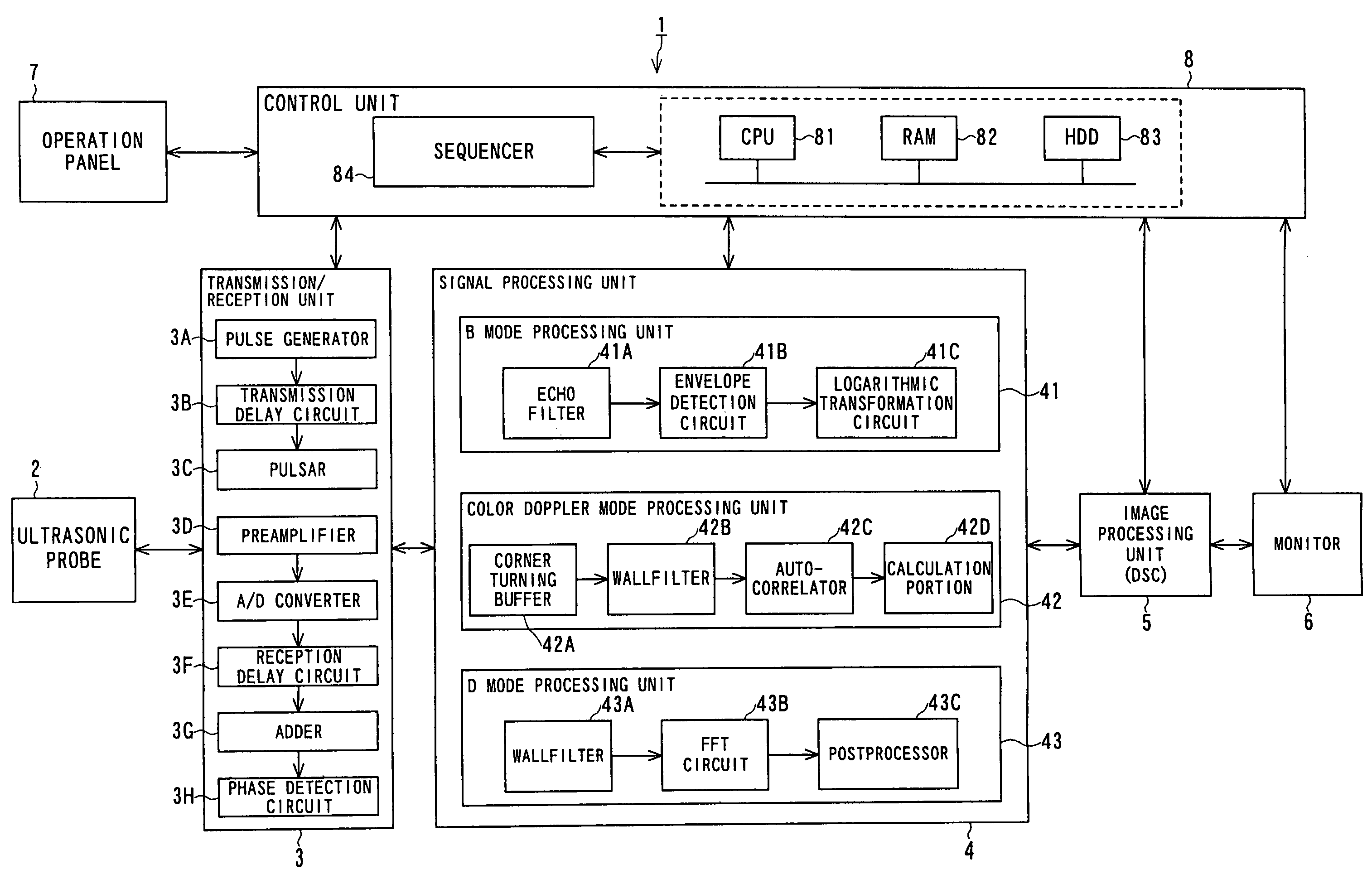
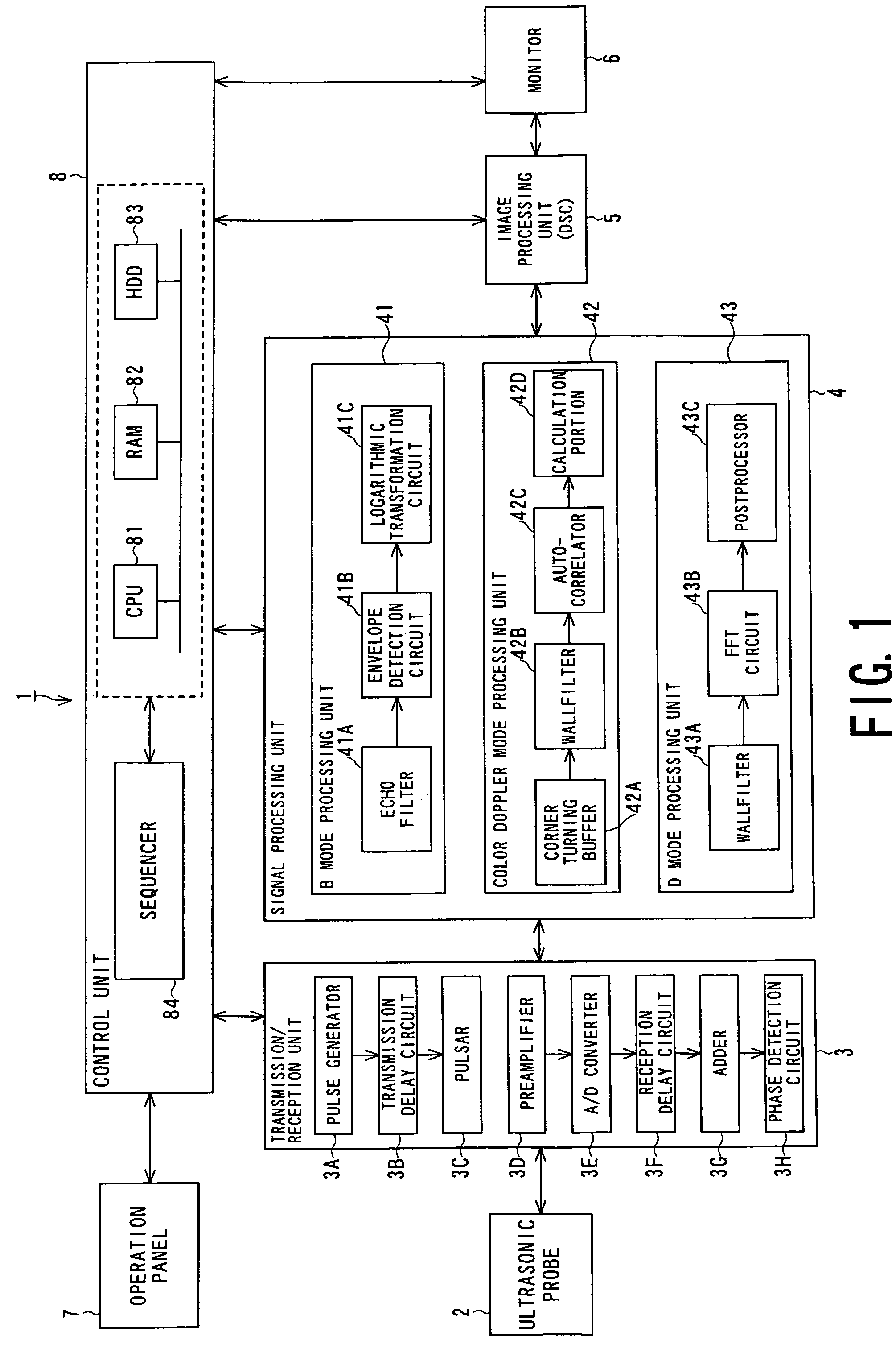
[0036]FIG. 1 is a block diagram showing a first embodiment of an ultrasonic diagnostic apparatus. An ultrasonic diagnostic apparatus 1 includes an ultrasonic probe 2 and a monitor 6. The ultrasonic probe 2 transmits and receives an ultrasonic wave to and from an object. The monitor 6 displays a two-dimensional configuration image, a two-dimensional blood-flow image and a Doppler spectrum image obtained by transmission and reception of ultrasonic waves. The ultrasonic diagnostic apparatus 1 also includes a transmission / reception unit 3, a signal processing unit 4 and an image processing unit 5, serving as a unit for several processing including signal processing. The transmission / reception unit 3, the signal processing unit 4 and the image processing unit 5 are arranged between the ultrasonic probe 2 and the monitor 6. The ultrasonic diagnostic apparatus 1 also includes a control unit 8 for controlling each of the elements 2, 3, 4, 5 and 6. The control unit 8 commu...

second embodiment

2. Second Embodiment

[0078]A second embodiment of the present invention will be described. A structure of an ultrasonic diagnostic apparatus according to the second embodiment is equivalent to that according to the first embodiment shown in FIGS. 1 and 2. Therefore, detail description of structure is omitted.

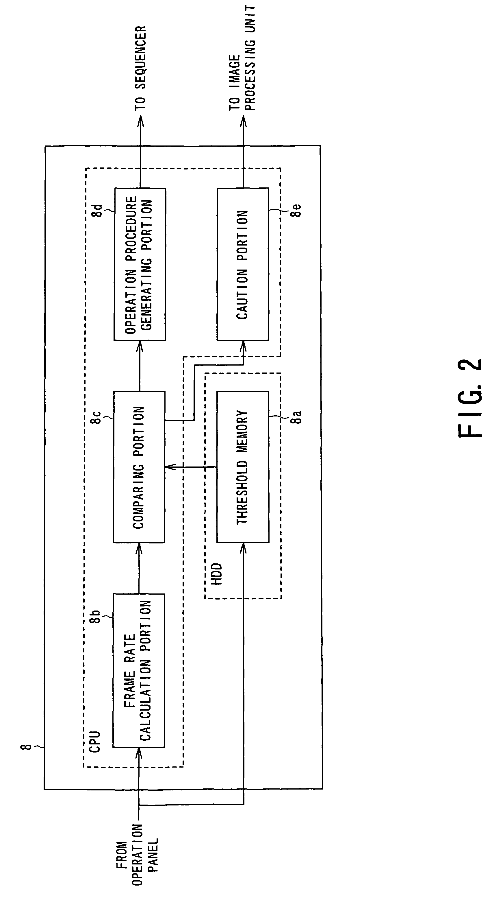
[0079]According to a second embodiment, when the frame rate is below the threshold, the operation procedure generating portion 8d generates an operation procedure specifying a scanning sequence in which the density of scanning lines is decreased in transmission / reception of ultrasonic waves in CFM mode scanning, in order to maintain the frame rate.

[0080]The operation procedure generating portion 8d generates an operation procedure specifying a scanning sequence in which the density of scanning lines of transmission / reception of ultrasonic waves in CFM mode scanning is decreased and B mode scanning is pushed forward in the generated time. Accordingly, in the B / CFM segment, the num...

third embodiment

3. Third Embodiment

[0091]A third embodiment of the present invention will be described. A structure of an ultrasonic diagnostic apparatus according to the third embodiment is equivalent to that according to the first embodiment shown in FIGS. 1 and 2. Therefore, detail description of structure is omitted.

[0092]In the ultrasonic diagnostic apparatus 1 according to a third embodiment, the operation procedure generating portion 8d changes the operation procedure of performing CFM mode signal processing to an operation procedure of performing P mode signal processing for generating a two dimensional blood flow image by a power Doppler mode. The power Doppler mode is a mode of displaying blood flow by detecting a Doppler shift and then obtaining a blood flow power value calculated based on the Doppler shift.

[0093]When the comparing portion 8c determines that the frame rate is lower than the threshold, the operation procedure generating portion 8d generates an operation procedure of speci...


PUM


Abstract

An ultrasonic diagnostic apparatus comprises a transmission and reception unit, a blood flow image generating unit, a Doppler spectrum image generating unit and a scanning sequence setting unit. The transmission and reception unit transmits first and second ultrasonic waves to an object and receive first and second echo signals from the object. The blood flow image generating unit generates a blood flow image from the first echo signals. The Doppler spectrum image generating unit generates a Doppler spectrum image from the second echo signals. The scanning sequence setting unit sets up a scanning sequence with mutual transmission and reception of the first and the second ultrasonic waves. The scanning sequence setting unit alters the scanning sequence into one having a modulated number of ensembles so as to make a frame rate of the blood flow image beyond a predetermined preset value.

Description

BACKGROUND OF THE INVENTION[0001]1. Field of the Invention[0002]The present invention relates to an ultrasonic diagnostic apparatus and an ultrasonic diagnostic method for obtaining an ultrasonic image by transmission and reception of an ultrasonic wave, and more particularly, to an ultrasonic diagnostic apparatus and an ultrasonic diagnostic method for displaying a blood flow image and a Doppler spectrum image simultaneously or almost simultaneously at least.[0003]2. Description of the Related Art[0004]In an observation of an object using an ultrasonic diagnostic apparatus, an operation mode called a triplex mode is used. The triplex mode is a composite mode for displaying a two dimensional configuration image, a two dimensional blood flow image, and a Doppler spectrum image simultaneously or substantially simultaneously.[0005]The two dimensional configuration image is a configuration image generated by converting the intensity of reflected ultrasonic waves to luminance. The two di...

Claims


Application Information

Patent Timeline
Patent Type & Authority Patents(United States)
IPC IPC(8): A61B8/06
CPCA61B8/06A61B8/13A61B8/463G01S7/52085G01S15/8979G01S7/52074G01S15/582
Inventor NAKATA, KAZUHITO
Owner TOSHIBA MEDICAL SYST CORP
Why Eureka
Try Eureka