Metal recovery system

a metal recovery and metal technology, applied in the field of metal recovery system, can solve the problems of virtually useless and worthless

Active Publication Date: 2012-04-17
GAWI
View PDF1 Cites 2 Cited by
  • Summary
  • Abstract
  • Description
  • Claims
  • Application Information

AI Technical Summary

Problems solved by technology

Metals in an appliance are often at the end of an appliance's life found intimately comingled such that they are virtually useless and worthless.

Method used


Image

  • Metal recovery system
  • Metal recovery system
  • Metal recovery system

Examples


example

[0024]Referring to FIG. 6 there is depicted a time / temperature curve for a tunnel kiln according the present invention that is designed for separating co-mingled aluminum, copper and iron from one another. This is accomplished by passing the co-mingled metals through tunnel kiln 10 at a constant rate and varying the temperature of kiln 10 and zones 32, 34, 36 and 38.

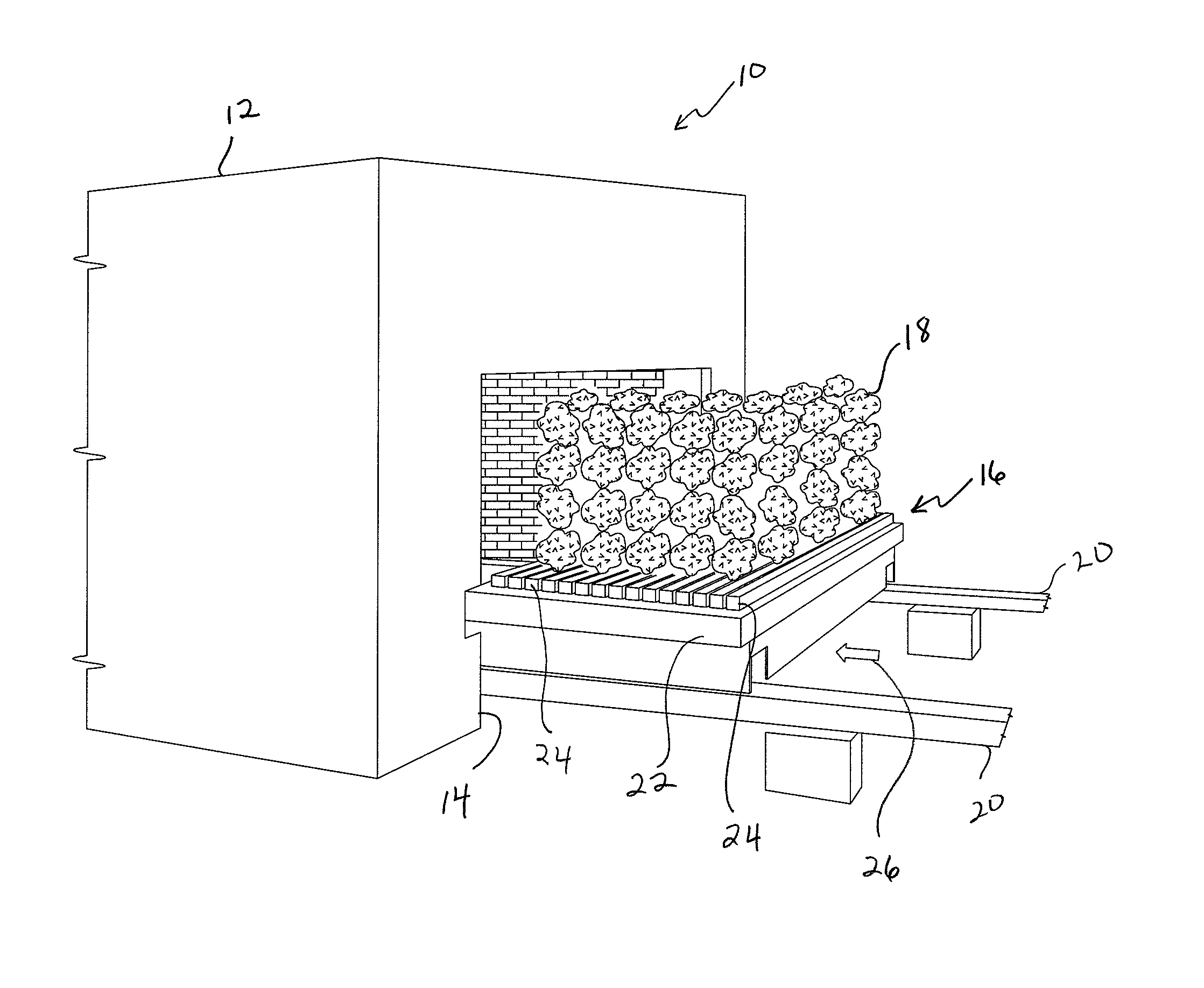
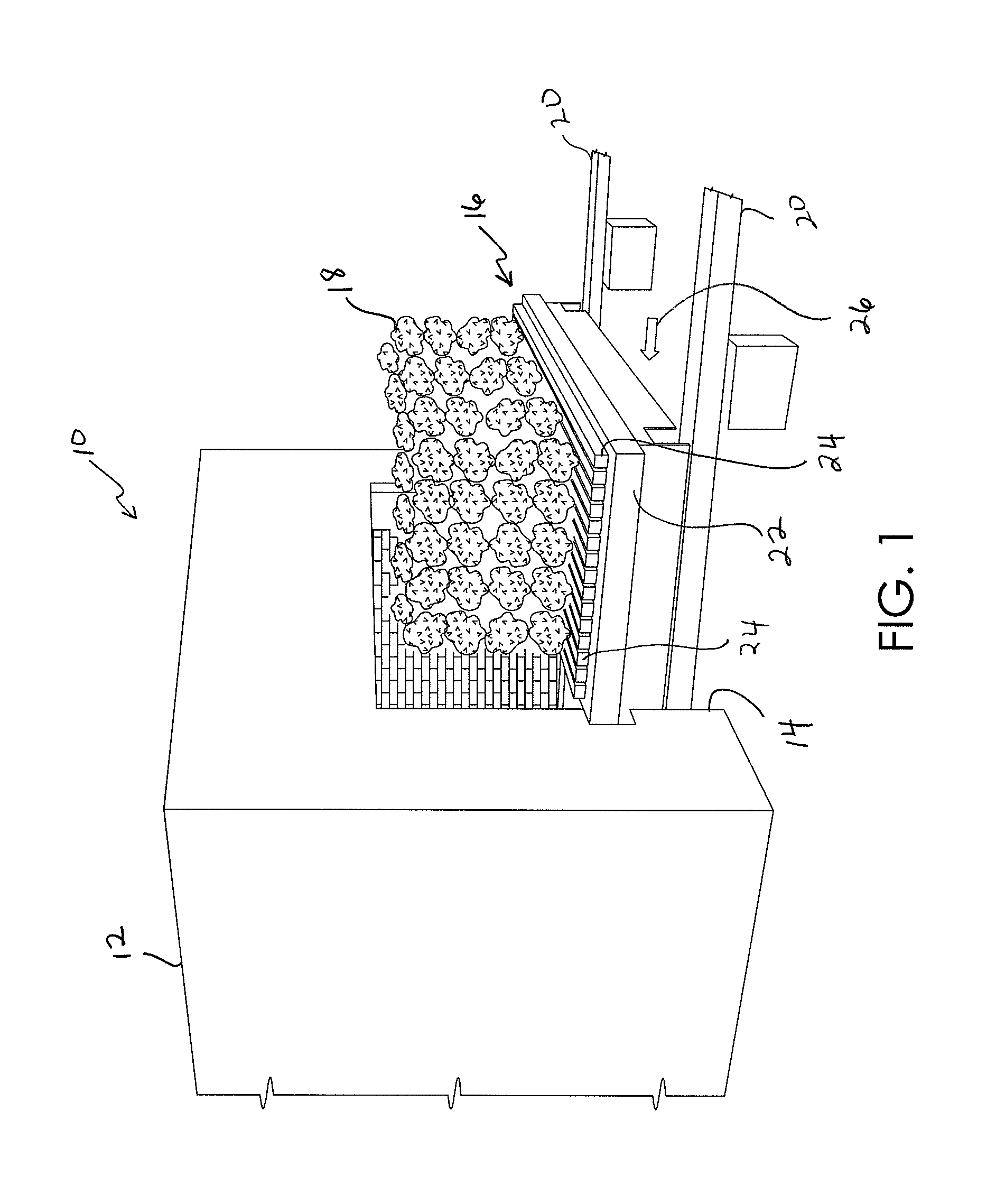
[0025]In this particular example, co-mingled metal units 18 containing aluminum, copper and iron are loaded onto refractory bars 24 of a conveyor element 16 and introduced into take off zone 32 of kiln 10 through entrance 14. Within take off zone, comingled metal units 18 are steadily heated from room temperature to about 400 degrees F. as they move in direction of travel 26. This step takes 1-hour to complete.

[0026]After pre-heat zone 34, comingled metal units 18 are pushed into pre-heat zone 34 where they are heated from 400 degrees F. up to 2,150 degrees F. in the span of 3 hours. During this rise in temperature the a...


PUM

PropertyMeasurementUnit
temperatureaaaaaaaaaa
lengthaaaaaaaaaa

Abstract

A thermal system for separating out co-mingled metals in almost pure form, the system including a tunnel kiln having temperature zones through which the co-mingled metals are conveyed and progressively heated until at least one metal of the co-mingled metals melts thereby separating the melted metal from the other metal or metals of the co-mingled metals. The system includes molten metal catch basins for collecting the melted metal which are arranged beneath a conveyor on which the co-mingled metals are transported within the kiln. The catch basins are tapped to the outside of the kiln so that as the various metals melt out at progressively higher temperatures, they can be collected into cast iron chills or other collection devices to form pure ingots.

Description

FIELD OF THE INVENTION[0001]The present invention is generally directed to a system and method for recovering metals. More particularly, the present invention is directed to a metal recovery system for recovering copper, aluminum and iron from scrapped electrical motors.BACKGROUND OF THE INVENTION[0002]A tunnel kiln is an elongated kiln or oven normally made of refractory material, through which ware such as brick, tile and like material may be continuously processed and transported as it is subjected to desired heating conditions. The ware is commonly transported through a tunnel kiln on flatbed ware cars which roll on rails extending through the length of the tunnel. The kiln is normally operated so that the tunnel is full of ware cars bumper to bumper. At certain intervals a new car is pushed into the entrance of the tunnel thereby ejecting a fully processed car of ware from the exit of the tunnel.[0003]Tunnel kilns are commonly divided into successive zones or sections in which ...

Claims


Application Information

Patent Timeline
Patent Type & Authority Patents(United States)
IPC IPC(8): C22B1/00
CPCC22B9/02C22B15/0056F27B9/20F27B9/24F27B9/26Y10S266/901Y02P10/20
Inventor FRAME, SCOTT WILLIAM
Owner GAWI
Why Eureka
Try Eureka