Mobile tunnel furnace

A tunnel kiln and mobile technology, applied in the field of tunnel kiln, can solve the problems of relying on manpower and lack of power devices, and achieve the effect of ensuring drying quality, less investment and good use effect.

Inactive Publication Date: 2007-03-14
魏胜英
View PDF1 Cites 24 Cited by
  • Summary
  • Abstract
  • Description
  • Claims
  • Application Information

AI Technical Summary

Problems solved by technology

This kind of annular turnover device also has the disadvantage of lacking a power device, and the kiln body can only be driven by manpower when moving.

Method used


Image

  • Mobile tunnel furnace
  • Mobile tunnel furnace
  • Mobile tunnel furnace

Examples


Embodiment Construction

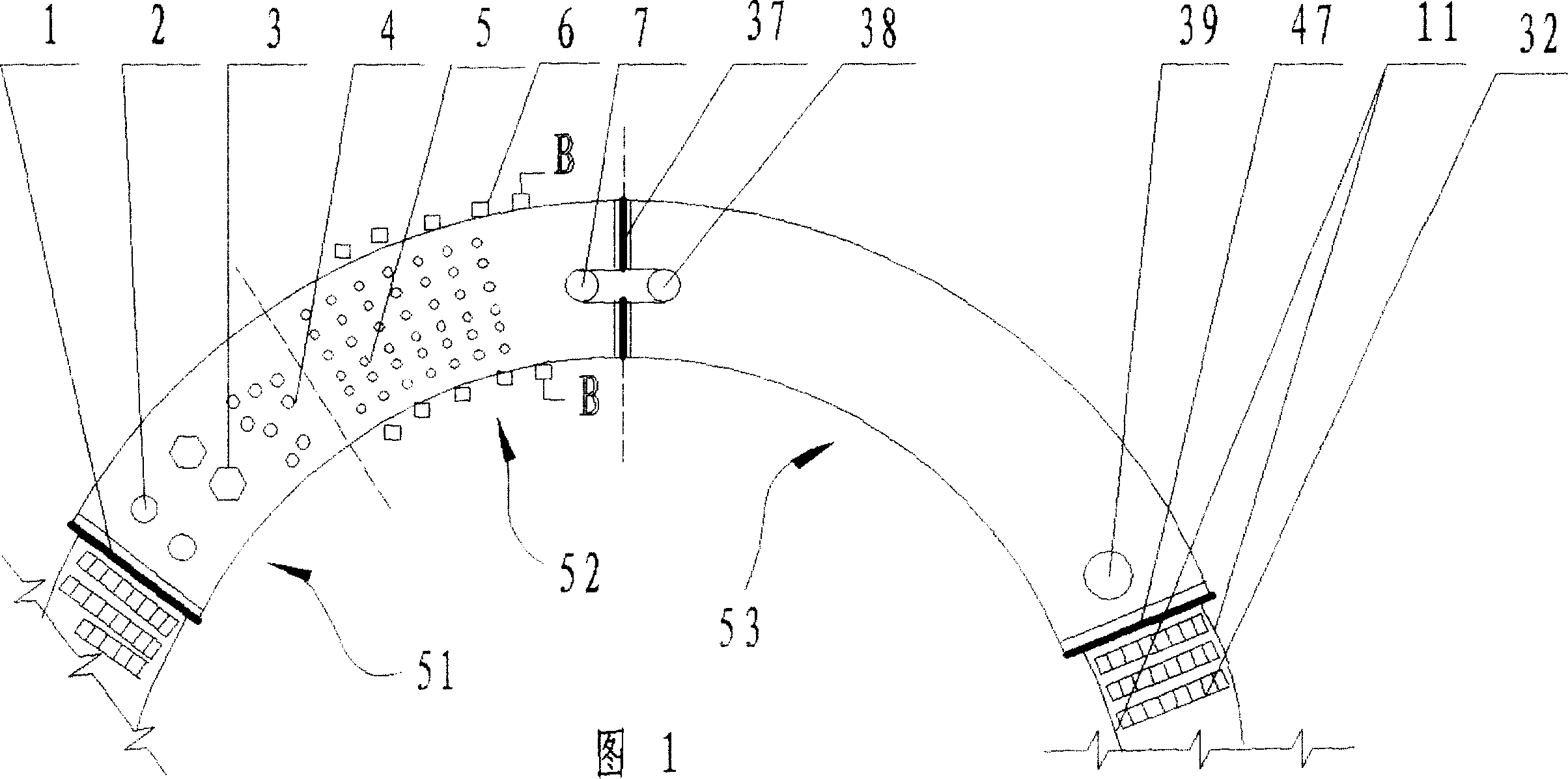
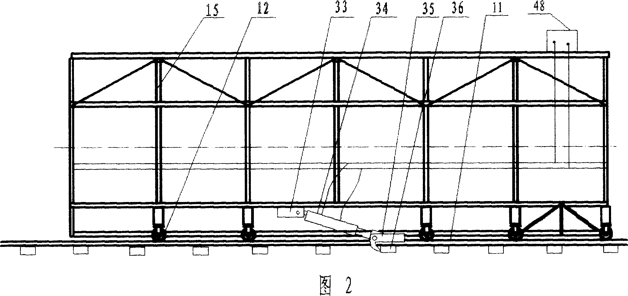
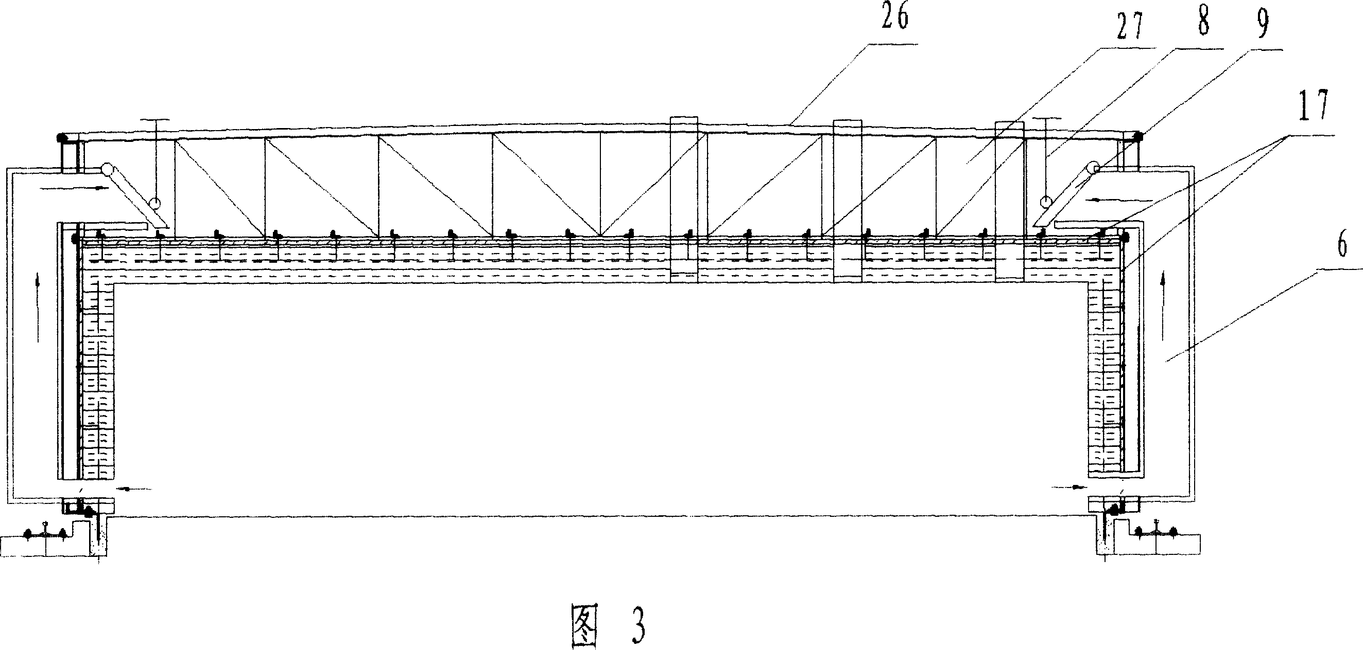
[0020] Referring to accompanying drawings 1-2, the kiln body of the mobile tunnel kiln of the present invention is made of a kiln frame and a heat-preserving refractory material fixed on the kiln frame, wherein the kiln frame is welded by profiles. The insulation refractory material adopts different materials for different sections. Rollers 12 are arranged on the kiln frame outside the kiln body, and the kiln body is placed on the ground track 11 through the rollers 12, and sleepers 10 are arranged at the lower part of the track. Power equipment is fixed on the kiln body, and the power equipment can be directly driven by connecting the motor and the reducer with the roller through the connecting rod mechanism; the diesel engine can also be used to drive the roller to rotate through the belt pulley. The power equipment of this embodiment adopts hydraulic equipment. That is, the power equipment of hydraulic cylinder plus hydraulic station.

[0021] As shown in Figure 2, an oil...


PUM


Abstract

The invention relates to a mobile tunneling kiln, comprising kiln body; moving wheel set on the two side of kiln body, by which kiln body is set on the ground railway; and power equipment set on the kiln body. Kiln body can be controlled manually and move in any time by the power equipment set on the kiln body in the invention. It is simple structure, low cost and good efficiency when power equipment is hydraulic device. Several doors of said kiln body is sealed in segmentation so that temperature in kiln body is improved quickly and adjusted or controlled.

Description

technical field [0001] The invention relates to clay product roasting equipment, in particular to a tunnel kiln with a movable kiln body for roasting clay products. Background technique [0002] The mobile tunnel kiln used to produce clay products in the prior art, as disclosed in Chinese patent 961187409 "Mobile tunnel kiln and the process layout of using the tunnel kiln to produce clay products", is provided with walking wheels on both sides of the kiln body. The walking wheels are placed on the circular tracks on both sides of the bottom of the kiln. The skeleton of the inner wall of the kiln is equipped with laminated layers of refractory fiber felt, which can lengthen the kiln body and add a drying area. The disadvantage of this mobile tunnel kiln is that there is no power device on the kiln body. Although the entire kiln body is placed on the ground rails through the walking wheels on both sides, the tens of meters long kiln body is difficult to move by manpower. The...

Claims


Application Information

Patent Timeline
Patent Type & Authority Applications(China)
IPC IPC(8): F27B13/00
Inventor 魏胜英
Owner 魏胜英
Why Eureka
Try Eureka