
Cross-pleated membrane cartridges, and method and apparatus for making cross-pleated membrane cartridges

a technology of membrane cartridges and cartridges, which is applied in the direction of fuel cells, trickle coolers, space heating and ventilation, etc., can solve the problems of large number of joints and edges that need to be sealed, limited durability, and high manufacturing cost of devices, so as to improve the flow of fluid streams and uniform layer spacing

Active Publication Date: 2012-04-17
CORE ENERGY RECOVERY SOLUTIONS INC
View PDF18 Cites 37 Cited by
  • Summary
  • Abstract
  • Description
  • Claims
  • Application Information

AI Technical Summary

Benefits of technology

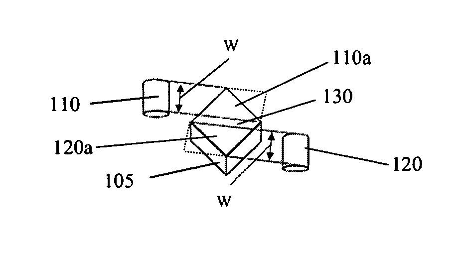
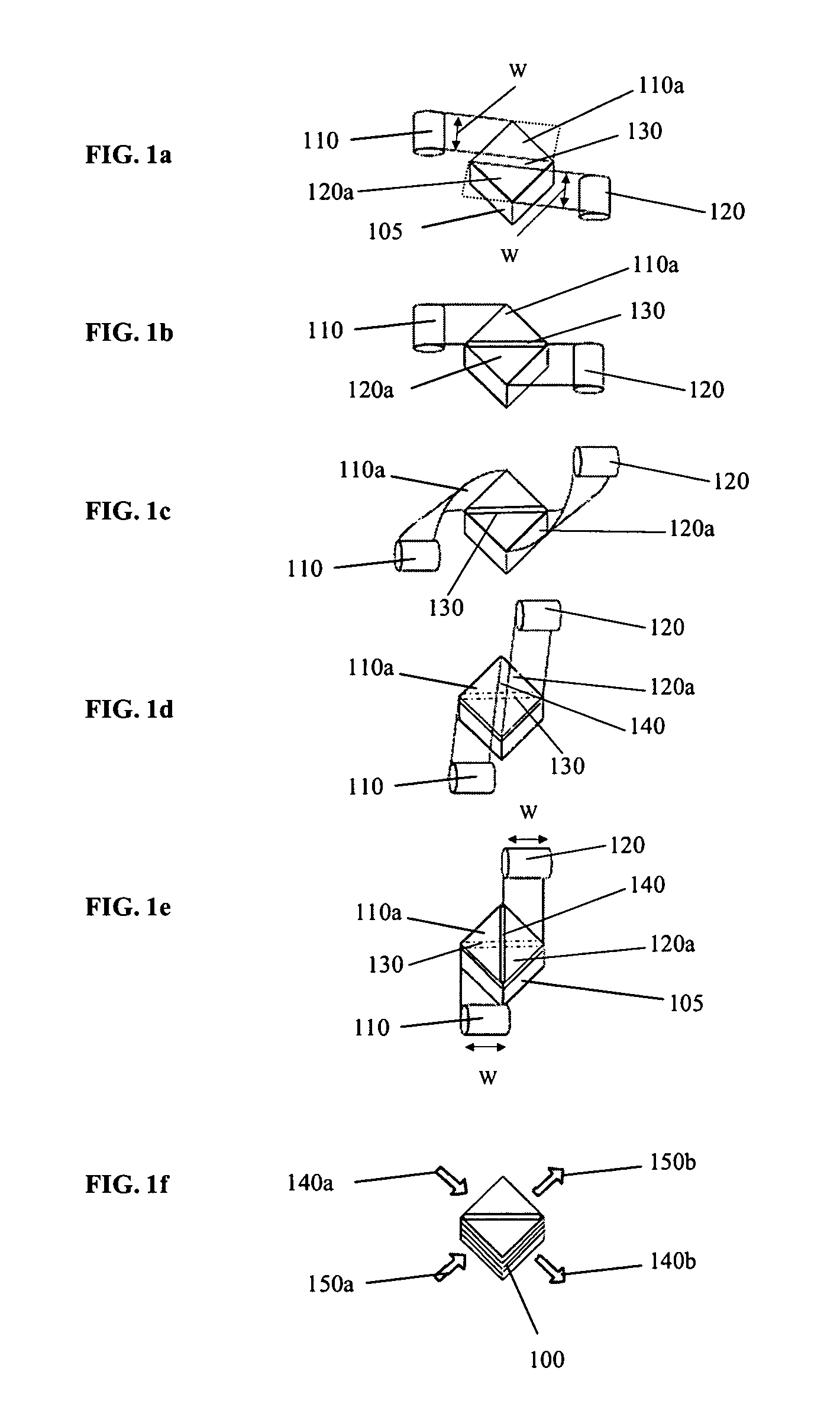
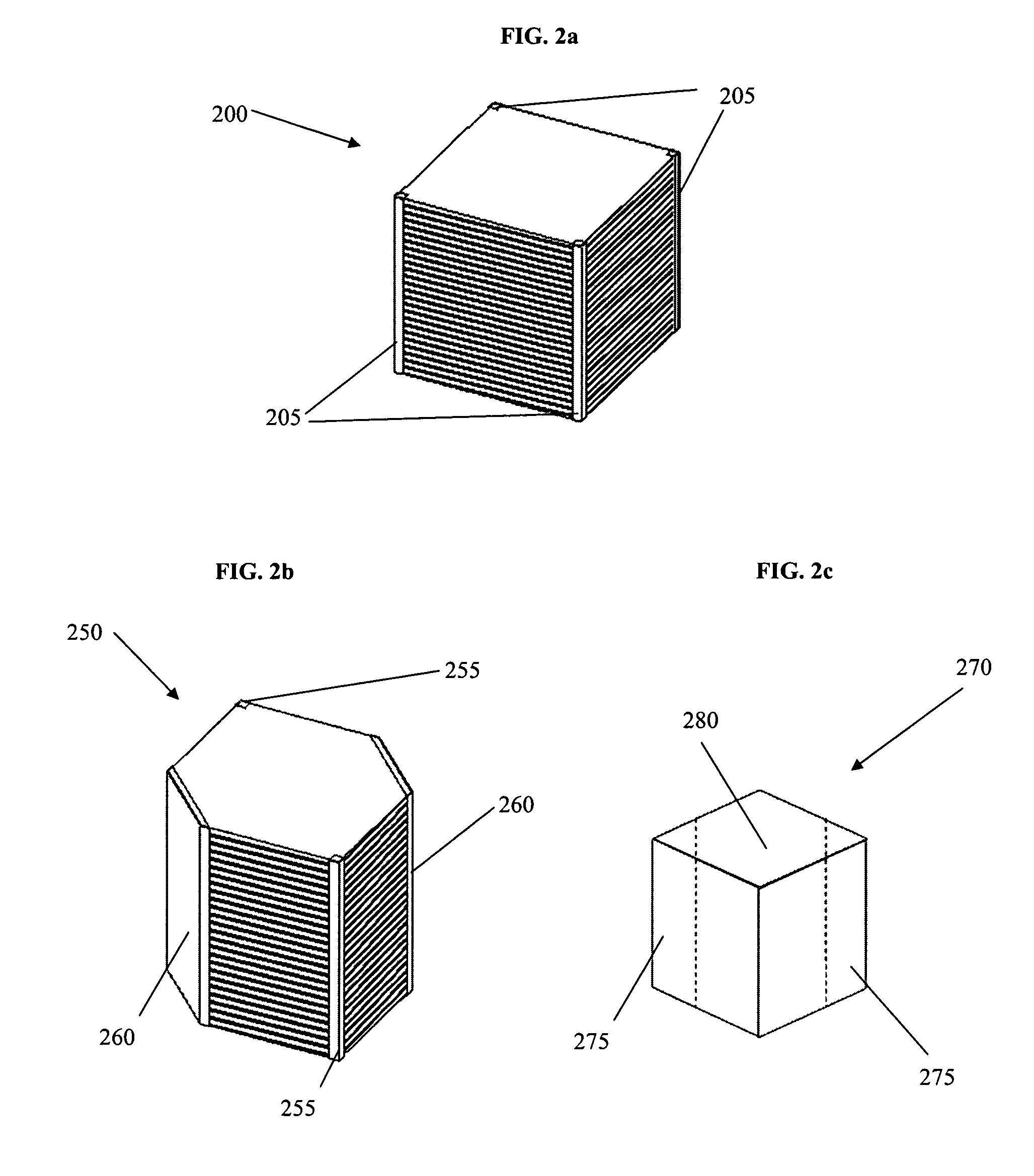
"The present invention is about a new type of membrane cartridge that has a unique arrangement of fluid passageways. The cartridge is made up of multiple layers of folded membrane that are sealed along edges to form a stack or layered array of fluid passageways. The membrane layers are joined by seams that are oriented at 90° to each other. The cartridge can be made in different shapes and can have more than two layers. The membrane strips can be joined by adhesive tape or other methods such as thermal weld or adhesive bond. The technical effects of this invention include improved fluid flow and better sealing of the membrane layers, as well as the ability to create a unique cross-pleated cartridge design."

Problems solved by technology

However, with plate-type planar exchangers there are a large number of joints and edges that need to be sealed.
As a result, such devices can be labor intensive and expensive to manufacture.
Also their durability can be limited, with potential delamination of the membrane from the frame and failure of the seals resulting in leaks, poor performance and cross-over contamination (leakage between streams).
However, the flow configurations that are achievable with concertina-style pleated membrane cartridges are limited, and there is still typically a need for some edge sealing.
Another disadvantage is the higher pressure drop as a result of the often smaller size of the entrance and exit areas to the pleated cartridge.

Method used


Image

  • Cross-pleated membrane cartridges, and method and apparatus for making cross-pleated membrane cartridges
  • Cross-pleated membrane cartridges, and method and apparatus for making cross-pleated membrane cartridges
  • Cross-pleated membrane cartridges, and method and apparatus for making cross-pleated membrane cartridges

Examples


Embodiment Construction

[0035]Cross-pleated cartridges of the type described herein have enhanced sealing characteristics. The particular folding configuration is advantageous in that it reduces the number of edges that have to be sealed, especially relative to plate-type heat and water vapor exchangers where individual pieces of membrane are stacked and have to be sealed along two edges, and even relative to pleated membrane devices with accordion-type pleated membrane cartridges. To a large extent, cross-pleated cartridges rely on the membrane folds (that occur along opposite edges of each layer) to seal and separate the fluid flows in adjacent streams. Thus, the overall number of seals, “seal area” or “seal length” tends to be lower. As a result, the tendency for leakage and cross-contamination of the process streams is greatly reduced. ERV cores comprising cross-pleated cartridges of the type described herein have given superior results in pressurized crossover leak-testing, relative to conventional pl...


PUM

PropertyMeasurementUnit
angleaaaaaaaaaa
angleaaaaaaaaaa
widthaaaaaaaaaa

Abstract

A membrane cartridge is manufactured by repeatedly folding and joining two strips of membrane to form a cross-pleated cartridge with a stack of openings or fluid passageways configured in an alternating cross-flow arrangement. The cartridge can be modified for other flow configurations including co-flow and counter-flow arrangements. Methods for manufacturing such cross-pleated membrane cartridges, as well as apparatus used in the manufacturing process are described. Cross-pleated membrane cartridges comprising water-permeable membranes can be used in a variety of applications, including in heat and water vapor exchangers. In particular they can be incorporated into energy recovery ventilators (ERVs) for exchanging heat and water vapor between air streams being directed into and out of buildings.

Description

CROSS-REFERENCE TO RELATED APPLICATIONS[0001]This application is related to and claims priority benefits from U.S. Provisional Patent Application Ser. No. 61 / 006,442, entitled “Cross-Pleated Heat and Humidity Exchanger”, filed on Jan. 14, 2008, which is hereby incorporated by reference in its entiretyFIELD OF THE INVENTION[0002]The present invention relates to cross-pleated membrane cartridges. More particularly the invention relates to cartridges in which the membrane is folded in a particular manner. The invention includes a method for manufacturing such cross-pleated membrane cartridges, as well as apparatus that can be used in the manufacturing method. The cartridges are useful in heat and water vapor exchangers and in other applications.BACKGROUND[0003]Heat and water vapor exchangers (also sometimes referred to as humidifiers) have been developed for a variety of applications, including building ventilation (HVAC), medical and respiratory applications, gas drying, and more rece...

Claims


Application Information

Patent Timeline
Patent Type & Authority Patents(United States)
IPC IPC(8): B01D53/22
CPCB01D46/0001B01D46/543B01D63/16B31D5/04F24F3/147F28D21/0015H01M8/04149B01D67/00B01D69/00B01D63/14B01D46/522B01D29/031F28F9/00B32B37/02B01D46/521Y10T156/1021H01M8/04141B01D2319/04B01D2313/44B01D53/228Y02E60/50B01D53/22B01D63/06Y10T156/1018Y10T156/102Y10T156/1715Y10T156/14Y10T156/1023Y10T428/24686Y10T156/1051Y10T156/1049B01D63/085B01D2313/14Y02P70/50Y02P70/10
Inventor MONTIE, GREGDEAN, JAMES FRANKLINMULLEN, CURTISHILL, ROBERT
Owner CORE ENERGY RECOVERY SOLUTIONS INC
Learn More