
Mass exchange contact device

a contact device and mass exchange technology, applied in the direction of liquid-gas reaction of thin-film type, separation process, fuel gas production, etc., can solve the problem that the ascending volatile phase flow cannot stably support the liquid phase in cyclic mode, the hydraulic resistance of the plate increases, and the speed of the volatile phase changes along the height of the column

Active Publication Date: 2012-04-17
MALETA BOGDAN +1
View PDF1 Cites 7 Cited by
  • Summary
  • Abstract
  • Description
  • Claims
  • Application Information

AI Technical Summary

Benefits of technology

[0017]A second aim of the present invention is the reduction of the metal content (amount of metal consumed for making the device), the height, and costs of the device, increasing the reliability and durability of device operation. Other aims of the invention may become apparent to a skilled artisan upon learning the present disclosure.
[0021]2) During the passing of gas (steam) to the contact element over the upper plate of the valve through the row of orifices and the bushing's interior, the dynamic thrust of the steam flow is deployed as an additional force, for support of the valve in the upper position.3) At a reducing or fluctuation of the gas (steam) expenditure for a fixed opening cross-section of the contact element for passing gas (steam) (for example 10%), meaning a decrease of pressure difference at the plate, the valve descends to the level of orifices row thereby creating a situational free cross-section for the flow of gas (steam) with a lower value (e.g. 2%), but still sufficient for support of the valve in the upper position due to stabilization of the pressure difference applied to the plate4) At a smooth closing of the gas (steam) flow, the valve, moving downwards, reduces the speed of its movement at the level of orifices row, and mildly, without an impact, touches the lower limiter (the bottom edge of the casing), thereby extending durability of the valve.

Problems solved by technology

The disadvantages of the mentioned device are: it's composed of two movable parts; there is a restriction of the opening cross-section of branch pipe for passing gas (steam), as well as a restriction of the ringed holes' opening cross-section for a liquid flow.
These disadvantages increase the plate's hydraulic resistance at the time of gas (steam) passing, and the time of transferring liquid from one plate to another.
A disadvantage of the above-mentioned devices is that the volatile phase changes its speed along the height of the column due to varying the share of the volatile phase.
Therefore, the ascending volatile phase flow cannot stably support the liquid phase in a cyclic mode.
Hence, empty zones appear within the structured packing elements, the phases move unevenly, causing low separation efficiency.
This prevents arranging an efficient mass-exchange process with separate movements (i.e. in a cyclic mode) of the phases in the column.
This disadvantage is conditioned by the fact that the packing element creates a resistance to the liquid phase moving along the mass-exchange tray, and a mass-exchange surface is formed only due to barbotage.
The mentioned above devices have also another disadvantage of stochastic formation of the mass-exchange surface on the trays, while the liquid is intermingled throughout the whole volume of liquid phase.
A shortcoming of the devices described in the last two patents is that the amount of costly catalyst used is high, which makes the devices expensive.
The related art devices also cannot control the speed of chemical reactions, since they don't provide for regulation of the time of introduction of the volatile phase into the column.

Method used


Image

  • Mass exchange contact device
  • Mass exchange contact device
  • Mass exchange contact device

Examples


first embodiment (

‘Parent’)

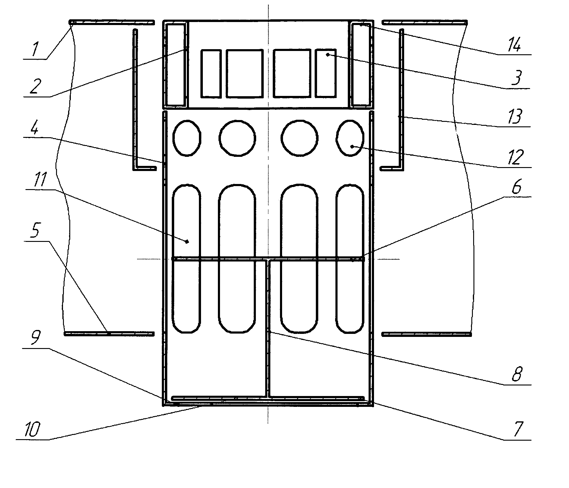
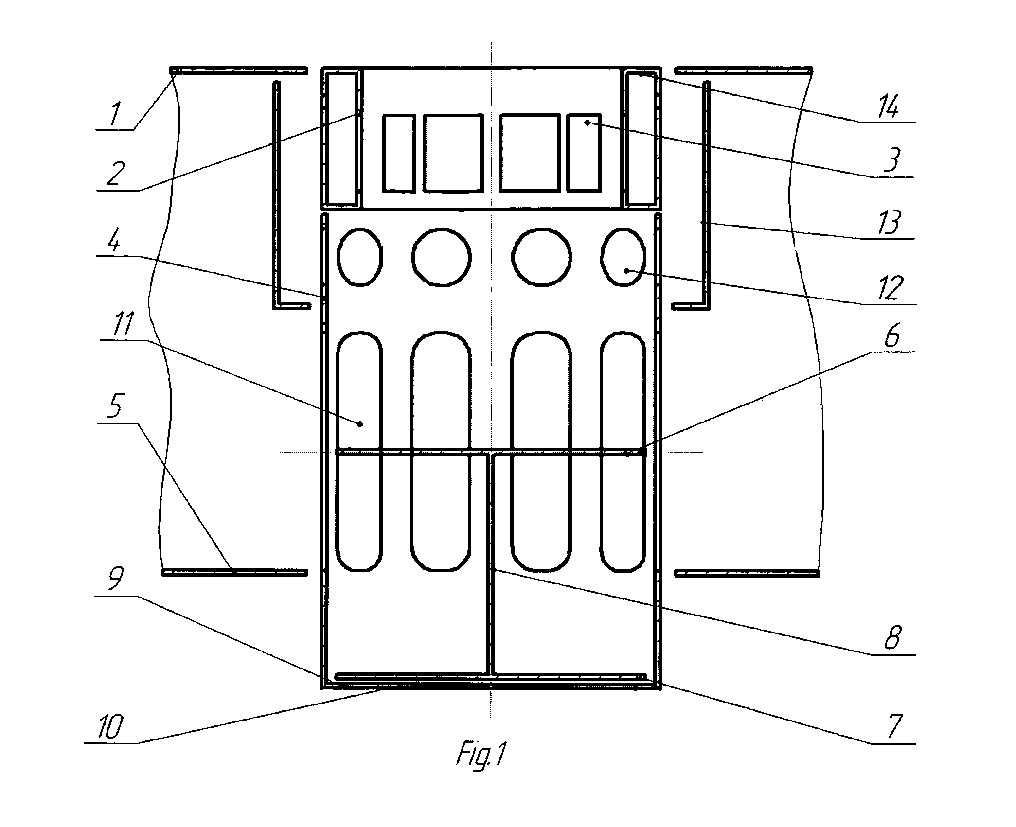
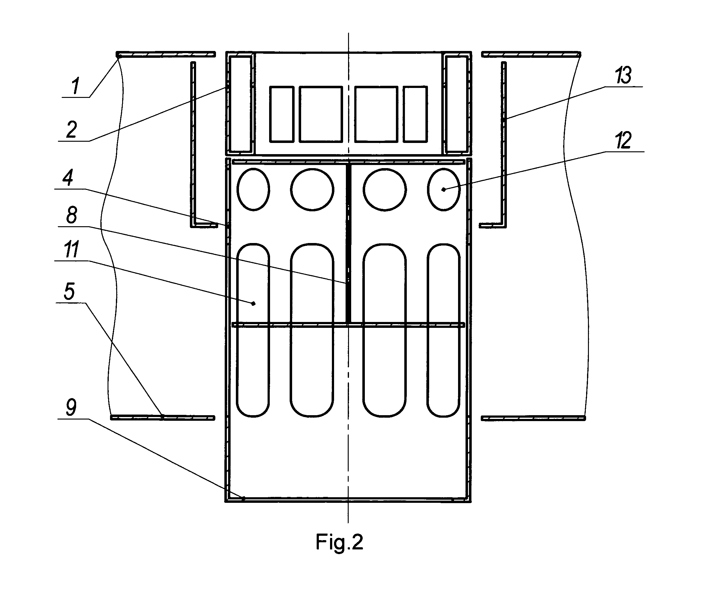
[0038]As illustrated on FIGS. 1, 2, 3, and 4, the contact device comprises an upper tray (1), a contact element (2) fixed to the upper tray 1, which contact element 2 includes a bottom opening and a barbotage unit (14) configured as an inner cap with strips (3) tangently bent out; an additional lower tray (5) disposed substantially in a parallel plane below the upper tray 1; a cylindrical casing (4) including a bottom opening (10), a ring-shaped descending limiter (9) formed inside the opening 10, a plurality of vertically extended windows (11) circumferentially disposed on the substantially vertical walls of the casing 4 (lower row) and a plurality of circular orifices (12) circumferentially disposed on the walls of the casing 4 (upper row) above the windows 11; a movable double-acting valve composed of an upper solid plate (6) and a lower solid plate (7) disposed above the plate 6, both the plates are fixedly attached to a distance rod (8) substantially vertically situate...

second embodiment (

‘Continuation’)

[0050]A common problem of the related art devices can be described as follows: an ideal mass-exchange process for separate movements of the liquid and volatile phases envisages a 100% intermingling of the phases during the introduction of the volatile phase, whose concentration changes during the mass-exchange process. In case of the 100% intermingling, the change of concentration xn of the volatile phase occurs during a time t of passage of the volatile phase throughout an entire volume of the liquid phase according to a dependence of dxn / dt. However, if one could orderly alter the concentration of the volatile phase along a height (z) of the liquid phase component, it would lead to an increase of the efficiency of separation of the liquid and volatile components on the mass-exchange tray according to a dependency of d2xn / dtdz.

[0051]This problem is herein solved in the second embodiment of inventive device / method for improvement of mass-exchange between a volatile ph...

third embodiment (

‘Continuation’)

[0062]The third embodiment of inventive device for improvement of mass-exchange between a volatile phase and a liquid phase is illustrated on FIGS. 8 and 9. The third embodiment basically includes elements identical to the elements of the second embodiment. However, according to the third embodiment, the space between the layers of package fittings 15 is filled out with a suitable conventional catalytic material (16), which increases the efficiency of the mass-exchange process in a column.

[0063]A column 20 (FIGS. 8 and 9), wherein catalytic distillation takes place, contains an upper row and a lower row of mass exchange contact devices, designed according to the first embodiment, wherein each of the rows is combined with a packing fitting 15 placed above thereof, and containing the catalytic material 16. FIG. 8 shows the state wherein the volatile phase is not introduced, whereas FIG. 9 shows the state wherein the volatile phase is introduced.


PUM

PropertyMeasurementUnit
distanceaaaaaaaaaa
sizeaaaaaaaaaa
hydraulic resistanceaaaaaaaaaa

Abstract

A mass-exchange contact device is proposed, comprising an upper tray, contact element including a barbotage unit configured as an inner cap with strips tangently bent out, a lower tray, a casing including a ring-shaped descending limiter, windows circumferentially disposed on the casing's walls (lower row), orifices circumferentially disposed on the casing's walls (upper row) above the windows, a double-acting valve composed of an upper and lower plates fixedly attached to a distance rod, and a cover bushing disposed coaxially to and around the upper region of casing embracing the contact element. Embodiments comprise a number of rows of the proposed devices situated one above the other, and separated by multi-layer packing fittings. In catalytic distillation columns, the fittings can be filled with catalytic material. Alternatively, the fitting is substituted with a grating that supports a catalytic granular layer. The device allows improving operation, reliability, durability, reducing its weight and costs.

Description

CROSS-REFERENCE TO RELATED APPLICATIONS[0001]This U.S. patent application is a continuation-in-part application of a pending U.S. patent application Ser. No. 12 / 225,575 (herein further referred to as “parent application”) filed on 24 Sep. 2008, entitled “Mass exchange contact device”, being a U.S. national phase application of a PCT application PCT / UA2007 / 000021 filed on 3 Apr. 2007, published as WO2007 / 117227, which PCT application claims priority of a Ukrainian patent application UA2006 / 03889 filed on 10 Apr. 2006, now Patent of Ukraine 5fo81700. The foregoing PCT applications and Ukrainian applications are hereby entirely incorporated by reference. The U.S. patent application Ser. No. 12 / 225,575 is hereby expressly abandoned.FIELD OF THE INVENTION[0002]The invention relates to mass exchange contact devices, namely to the devices used for performing mass exchange processes in a gas (steam)-liquid system in the conditions of a cyclic mode (at separate movements of the gas / liquid ph...

Claims


Application Information

Patent Timeline
Patent Type & Authority Patents(United States)
IPC IPC(8): B01J8/02F02M29/04B01J8/00B01J10/00B01J19/00B01J35/02
CPCB01D3/163
Inventor MALETA, BOGDANMALETA, OLESJA
Owner MALETA BOGDAN
Learn More