Method for the modernization of a urea production plant

a technology of urea production and modernization, which is applied in the preparation of urea derivatives, liquid gas reaction processes, organic compound preparations, etc., can solve the problems of high cost and inefficient thermal stripping process, so as to improve the carbamate stripping process and improve the efficiency of the conventional self-stripping plant , the effect of reducing the cos

Active Publication Date: 2012-04-17
CASALE SA
View PDF10 Cites 2 Cited by
  • Summary
  • Abstract
  • Description
  • Claims
  • Application Information

AI Technical Summary

Benefits of technology

[0019]In a first embodiment of the inventive process, the existing shell-and-tube kettle condenser is maintained. In particular, the existing kettle condenser can be maintained to reduce cost if an increase of the condensation capacity is not desired.
[0020]In a second embodiment, the condensing capacity is increased by adding at least one further condenser in parallel or in series with the existing one.
[0024]The invention has the following advantages. Use of part of the carbon dioxide feed as a stripping agent improves the carbamate stripping process and has been found advantageous also with no increase of the condensing capacity.
[0025]In particular, it has been found that efficiency of a conventional self-stripping plant can be improved in a surprisingly manner at a lower cost than prior-art processes involving the necessary provision of new items such as a new stripper and / or condenser.
[0026]The provision of a new submerged vertical condenser has the further advantage of an increased production of urea due to conversion of carbamate into urea taking place in the tubes of the condenser. Hence, reaction capacity is increased without modification of the reactor or provision of a more expensive pool condenser.
[0027]Another advantage is that the improved stripping reduces the content of ammonia in the urea solution from the stripping section; hence, the duty of the subsequent treatment section is reduced with the effect of a de-bottlenecking of the whole plant.

Problems solved by technology

The self-stripping process however has some drawbacks, that may have a negative influence also on the possibility of an attractive revamping.
A first drawback is that the efficiency of the thermal stripping is not optimal, especially in terms of removal of ammonia.
The process of WO '1083 is however still expensive, involving the provision of new equipments (new CO2 stripper and / or new condenser) or substantive modification of the existing one(s).

Method used


Image

  • Method for the modernization of a urea production plant
  • Method for the modernization of a urea production plant

Examples


Embodiment Construction

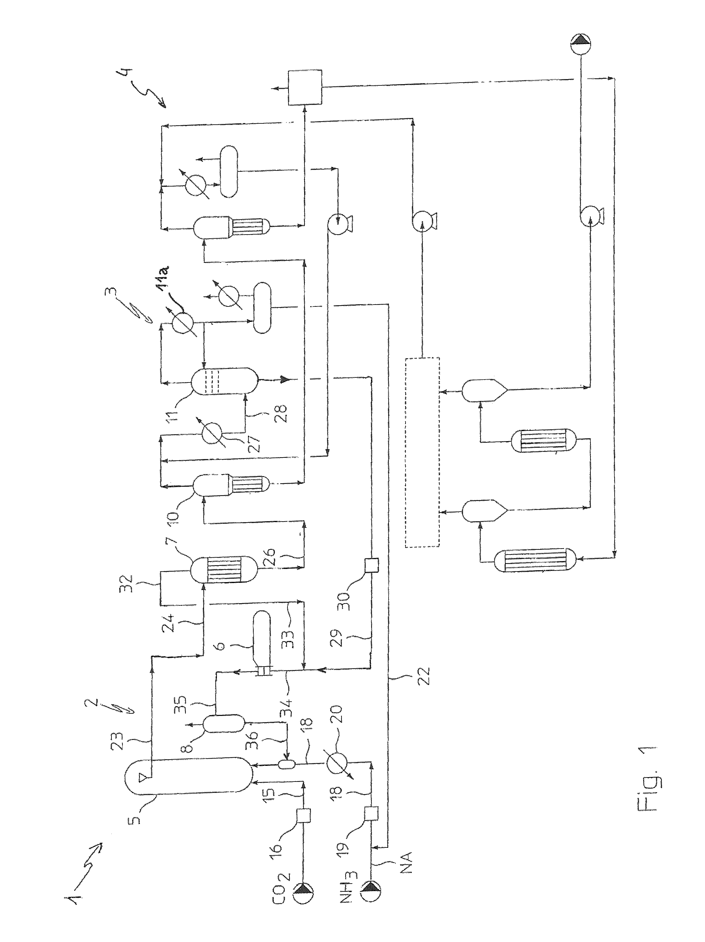
[0034]FIG. 1 is a layout of a conventional self-stripping or thermal stripping urea plant 1. The scheme is simplified and reference will be made only to details which are useful to understand the present invention.

[0035]The plant 1 comprises a high-pressure synthesis section or synthesis loop 2 operating for example at around 150 bar; a medium-pressure treatment section 3 operating at 15-25 bars, and a low-pressure urea recovery section 4.

[0036]The synthesis loop 2 comprises a reactor 5, a condenser 6 and a stripper 7 operating substantially at the same pressure as well as a scrubber 8.

[0037]The condenser 6 is a horizontal shell-and-tube kettle unit receiving an input 34 of carbamate solution from the medium-pressure section via line 29, and gaseous phases discharged by stripper 7 via line 32, 33. Condensation is effected on the tube side, and the condensation heat is used to produce steam.

[0038]The stripper 7 is substantially a tube-bundle, steam-heated exchanger. The carbamate sol...


PUM

PropertyMeasurementUnit
pressureaaaaaaaaaa
pressureaaaaaaaaaa
pressureaaaaaaaaaa

Abstract

A method for revamping a conventional self-stripping urea plant is disclosed, where a minor portion (18a) of the carbon dioxide feed is fed to the stripper (7) and used as a stripping agent. In further embodiments, another carbamate condenser is installed, or the conventional horizontal shell-and-tube carbamate condenser (6) is replaced with a vertical submerged unit.

Description

FIELD OF THE INVENTION[0001]The present invention discloses a method for revamping and increasing the capacity of a self-stripping urea plant.PRIOR ART[0002]The self-stripping or thermal-stripping process is a well known process for the synthesis of urea. It is often referred to as the Snamprogetti process, having been developed by Snamprogetti in the late 60s. A disclosure of the process and related plant can be found for example in GB 1542371. Many urea plants are using this process worldwide.[0003]Basically, the self-stripping process provides reaction between ammonia and CO2 in a high pressure reactor around 150-160 bar and N / C ratio usually around 3.2-3.4 molar; the solution containing ammonia and unconverted ammonium carbamate discharged by the reactor is heated in a high-pressure stripper to decompose the carbamate and recover ammonia. A vapour phase containing ammonia and CO2 produced in the stripper is condensed in a high-pressure condenser, which is part of a high-pressure...

Claims


Application Information

Patent Timeline
Patent Type & Authority Patents(United States)
IPC IPC(8): C07C273/00
CPCC07C273/04B01J2219/00024
Inventor ZARDI, FEDERICOSCOTTO, ANDREA
Owner CASALE SA
Why Eureka
Try Eureka