Switch circuit of DC/DC converter configured to conduct various modes for charging/discharging

a technology of dc/dc converter and switch circuit, which is applied in the direction of dc-dc conversion, power conversion system, instruments, etc., can solve the problems of reducing the efficiency of the converter, unable to achieve maximum efficiency, and unable to achieve the effect of maximum efficiency

Active Publication Date: 2012-04-17
INNOLUX CORP
View PDF3 Cites 91 Cited by
  • Summary
  • Abstract
  • Description
  • Claims
  • Application Information

AI Technical Summary

Benefits of technology

[0012]Therefore, it is an object of the invention to provide an increased number of different boosting factors with a charge-pump type DC / DC converter at maximum efficiency.

Problems solved by technology

However, sometimes the circuitry requires a larger voltage than the battery voltage in order to operate.
This however reduces the efficiency of the converter, as the voltage drop over the switches corresponds to additional power loss.
This reduced efficiency has a significant impact on power consumption which is an important point of attention in mobile applications.
However, maximum efficiency can only be achieved at three different boosting factors (ignoring losses) using such charging in either series or parallel connection and discharging in either series or parallel connection.

Method used


Image

  • Switch circuit of DC/DC converter configured to conduct various modes for charging/discharging
  • Switch circuit of DC/DC converter configured to conduct various modes for charging/discharging
  • Switch circuit of DC/DC converter configured to conduct various modes for charging/discharging

Examples


first embodiment

[0037]FIG. 5A and FIG. 5B schematically show a DC / DC converter using three charge pump capacitors according to the invention.

[0038]FIG. 5A schematically shows the DC / DC converter 10. The DC / DC converter is arranged to convert an input voltage Vin to an output voltage Vout, both measured relative to a reference voltage GND, typically ground. The DC / DC converter has a first charge pump capacitor C1 with first electrode C1a and second electrode C1b, a second charge pump capacitor C2 with first electrode C2a and second electrode C2b and a third charge pump capacitor C3 with first electrode C3a and second electrode C3b.

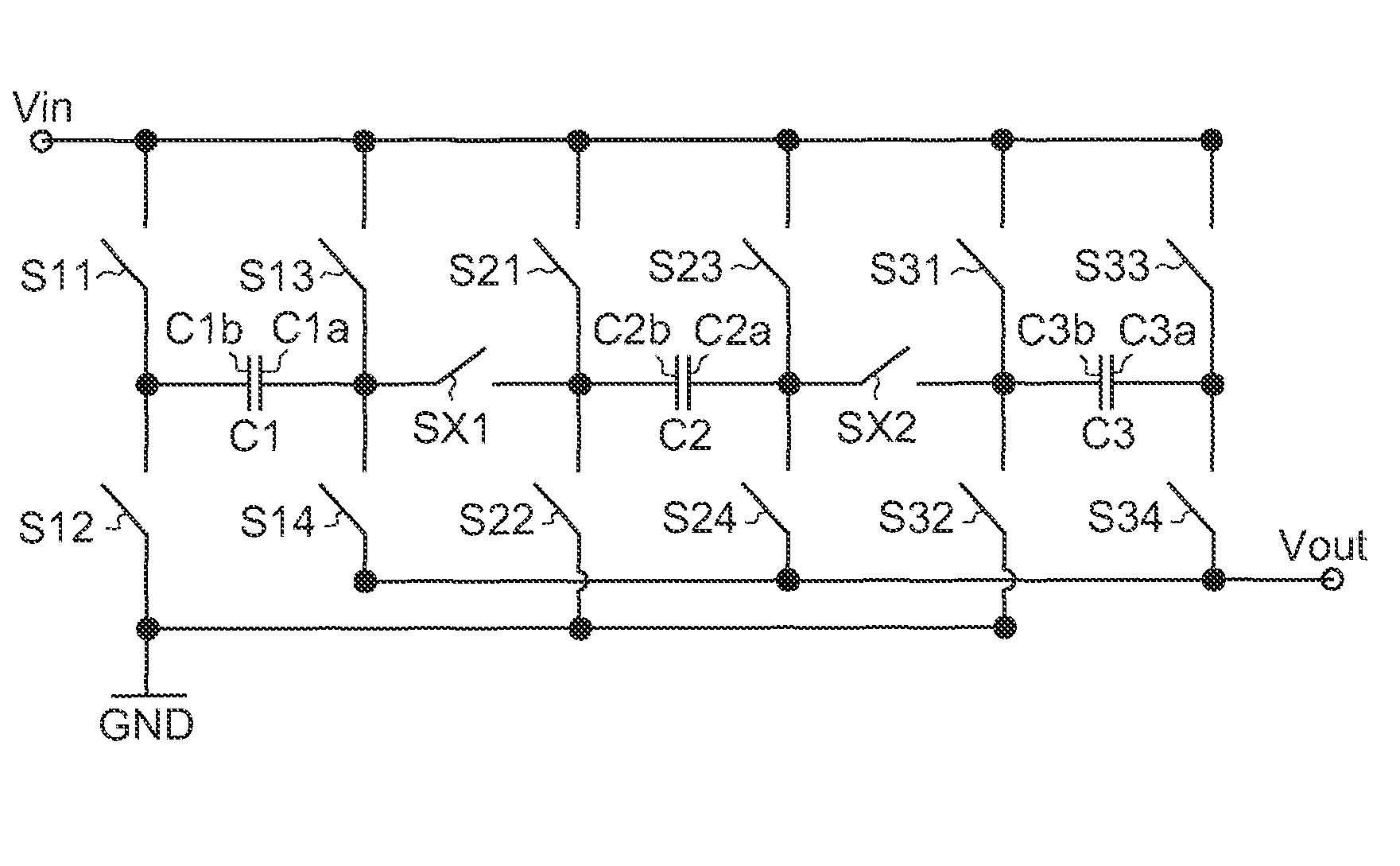
[0039]As shown in FIG. 5B, a switch circuit 20 of the DC / DC converter comprises a first circuitry associated with the first charge pump capacitor C1, a second circuitry associated with the second charge pump capacitor C2, and a third circuitry associated with the third charge pump capacitor C3. The switch circuit 20 further comprises four switches S11, S12, S13, S14 assoc...

second embodiment

[0049]For providing more modes in the charge phase and / or discharge phase, the invention provides a third further switch SXX between the first electrode C1a of the first charge pump capacitor C1 and the second electrode C3b of the third charge pump capacitor C3 as is shown in FIG. 8. The third further switch SXX can thus connect the first charge pump capacitor C1 and the third charge pump capacitor C3 in series, while bypassing the second charge pump capacitor C2. FIG. 8 further comprises the same arrangement of switches and charge pump capacitors as FIG. 5B.

[0050]With the addition of the third further switch SXX, new modes can be provided in the charge phase and / or discharge phase, and new combinations of modes in the charge phase with modes in the discharge phase can be provided, for providing new gain factors and thus providing new boosting factors with maximum efficiency.

[0051]FIG. 9A-FIG. 9C and FIG. 10A-FIG. 10C schematically show examples of additional modes in charge and dis...


PUM


Abstract

A DC / DC converter includes an input terminal for receiving an input voltage; an output terminal for providing an output voltage; a ground terminal for providing a reference voltage; a plurality of charge pump capacitors including at least a first charge pump capacitor, a second charge pump capacitor, and a third charge pump capacitor; and a switch circuit. The switch circuit includes a plurality of switches configured to allow the plurality of charge pump capacitors connected in a hybrid parallel-series arrangement between the input terminal and the ground terminal or between the input terminal and the output terminal by selectively conducting a specified portion of the switches.

Description

CROSS REFERENCE TO RELATED PATENT APPLICATION[0001]This patent application claims the benefit of U.S. provisional patent application No. 61 / 165,521, filed Apr. 1, 2009.FIELD OF THE INVENTION[0002]The invention relates to a DC / DC converter including a switch circuit configured to conduct a variety of modes for charging / discharging of the DC / DC converter. The invention also relates to a switch circuit for use in such a DC / DC converter and an apparatus including such a DC / DC converter.BACKGROUND OF THE INVENTION[0003]A portable apparatus is usually powered from a battery. The battery delivers a battery voltage to a circuitry of the portable apparatus. However, sometimes the circuitry requires a larger voltage than the battery voltage in order to operate. Moreover, the larger voltage is typically also required to be a substantially stable pre-determined voltage, e.g. with a predetermined voltage level of 5.5 V. For this purpose, a DC / DC converter is used to convert an input voltage, suc...

Claims


Application Information

Patent Timeline
Patent Type & Authority Patents(United States)
IPC IPC(8): H02M3/18
CPCH02M3/07
Inventor YEATES, DAVID JULIAN
Owner INNOLUX CORP
Why Eureka
Try Eureka