Methods for noise validated phase ranging RFID location

a phase ranging and noise validation technology, applied in the field of touch free identification, location and/or tracking systems, can solve the problems of inability to enable the three-dimensional location of the target rfid within the volume, inability to further input, and inability to inhibit the intersection triangulation of interrogation signal beams, etc. cost, installation and maintenance, and the effect of multiple sasl hardwar

Active Publication Date: 2012-04-17
RF CONTROLS
View PDF17 Cites 16 Cited by
  • Summary
  • Abstract
  • Description
  • Claims
  • Application Information

AI Technical Summary

Benefits of technology

[0019]Through investigation of the operational parameters of RFID object location systems, the inventors have recognized that analysis of the phase of the received signal from a target RFID over multiple interrogation frequencies can provide ranging of the target RFID distance along the interrogation signal beam with significant precision.
[0024]The transceiver 22 is preferably provided with frequency hopping capability to enable multiple high speed RFID tag 38 scans over a range of frequencies, for example between 902 to 928 Mhz, at the same beam steering angle, generating a data set for each frequency. Frequency hopping may be, for example with steps of 100, 250 or 500 kHz, resulting in 250, 100 or 50 steps over the frequency range. Government radio frequency regulations may require a minimum frequency hopping rate of 50 frequency changes within 20 seconds. Faster frequency changes may enable increased scanning / calculation speeds.
[0032]Further refinements may be applied that reduce overall processing times and also improve noise immunity. For example, the distances of MIN and MAX may be reduced to a high probability range by utilizing signal timing and / or RSSI data of the data sets to reduce the theoretical length of the beam extent. If signal timing indicates a short or long period between launch of the interrogation signal and reception of the backscatter modulation from the target RFID tag a segment of the beam extent closer and / or farther away from the antenna 18 may be prioritized for examination. Similarly, if the RSSI reading is higher and / or lower, this may be interpreted as an indication that the range of possible locations of the target RFID along the signal beam is closer and / or farther away.
[0048]One skilled in the art will appreciate that the apparatus and systems disclosed provide significant equipment, installation and maintenance advantages over prior multiple antenna 18 triangulation and / or significant improvements in location precision compared to single antenna 18 tag location systems without phase ranging capability.

Problems solved by technology

However, ranging of the distance from the antenna to the position along the beam where the target RFID is located, to enable three-dimensional location of the target RFID within the volume, is impossible without further inputs.
Barriers and / or products in a typical volume at any moment during use may create obstructed scanning areas for one or more of the SASL, preventing the scanning of a target RFID by at least two SASL and thus inhibiting interrogation signal beam intersection triangulation location of the target RFID.
Further, costs for multiple SASL hardware, installation and maintenance may become significant.
However, location accuracy utilizing these alternative methods may be less than satisfactory where RFID location with high precision is desired.

Method used


Image

  • Methods for noise validated phase ranging RFID location
  • Methods for noise validated phase ranging RFID location
  • Methods for noise validated phase ranging RFID location

Examples


Embodiment Construction

[0019]Through investigation of the operational parameters of RFID object location systems, the inventors have recognized that analysis of the phase of the received signal from a target RFID over multiple interrogation frequencies can provide ranging of the target RFID distance along the interrogation signal beam with significant precision.

[0020]Phase ranging as used herein is the procedure of calculating the distance a tag is from the RFID location system antenna along the interrogation signal beam, based upon the phase readings included in the data set(s) obtained for each frequency at the same steering angle.

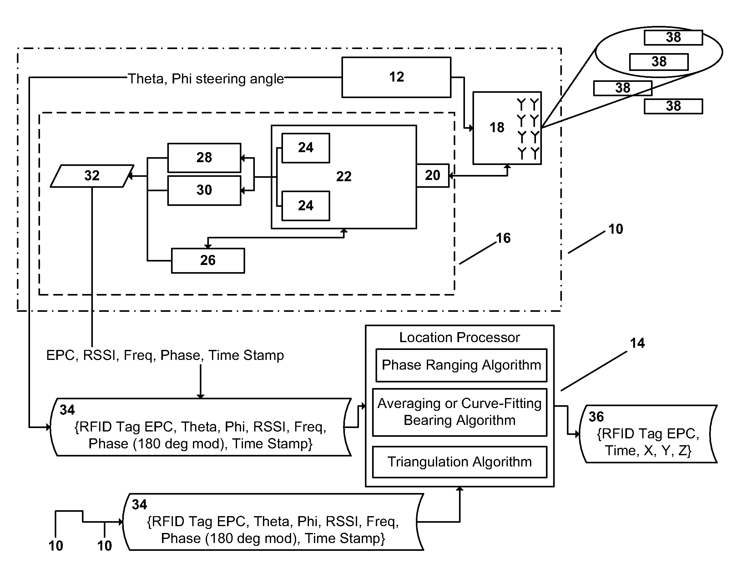
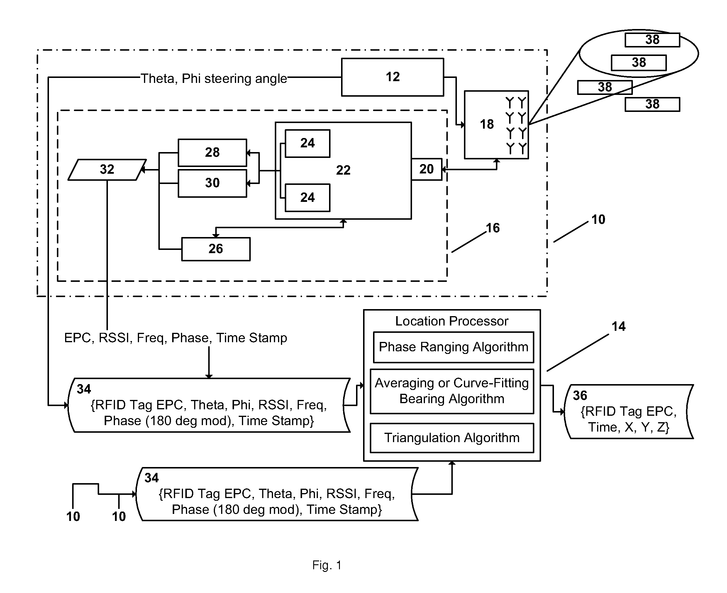
[0021]FIG. 1 demonstrates an exemplary RFID location system with signal phase detection and phase ranging capability. The intelligent steerable phased array antenna module 10 is demonstrated with a beam steering unit 12 under the control of a location processor 14. An RFID reader module 16 directs an interrogation signal to and receives corresponding signals from the steerable...


PUM


Abstract

A method and apparatus for validating a distance output of a phase ranging RFID location system, based upon the phase readings included in data sets obtained from monitoring reply signals corresponding to interrogation signals at multiple frequencies and a common interrogation signal beam direction; by comparison of measured phase and frequency data sets with theoretical phases calculated with respect to the same frequencies over a range of positions corresponding to a beam extent of the interrogation signal. The distance output validated by comparison with theoretical threshold data processed to generate an extreme values distribution from which a cumulative distribution function is extracted and against which a confidence level is applied.

Description

CROSS REFERENCE TO RELATED APPLICATIONS[0001]This application is a continuation-in-part of commonly owned co-pending U.S. Utility patent application Ser. No. 12 / 580,365, titled “Phase Ranging RFID Location System” filed Oct. 16, 2009 by Russell Hofer and Graham P. Bloy, hereby incorporated by reference in its entirety.BACKGROUND[0002]1. Field of the Invention[0003]The invention relates to touch free identification, location and / or tracking systems. More particularly, the invention relates to an RFID identification, location and / or tracking system utilizing noise validated phase ranging to determine the distance of a target RFID from the system antenna.[0004]2. Description of Related Art[0005]Commonly owned PCT Patent Application Publication WO 2009 / 035723, titled “Radio Frequency Signal Acquisition and Source Location System” by Bloy et al published Mar. 19, 2009, hereby incorporated by reference in its entirety, discloses a real-time RFID location system that utilizes an Intelligen...

Claims


Application Information

Patent Timeline
Patent Type & Authority Patents(United States)
IPC IPC(8): G08C19/16
CPCG01S3/46G01S13/84G01S13/825
Inventor HOFER, RUSSELLBLOY, GRAHAM P. A.
Owner RF CONTROLS
Why Eureka
Try Eureka