
Liquid crystal display device

a liquid crystal display and display angle technology, applied in the field of liquid crystal display devices, can solve the problems of display quality varies, grayscale characteristic ( characteristic) is dependent on viewing angle, etc., and achieve the effect of reducing the dependence of viewing angle on grayscale characteristic (color reproducibility) of the liquid crystal display devi

Inactive Publication Date: 2012-04-17
SHARP KK
View PDF21 Cites 28 Cited by
  • Summary
  • Abstract
  • Description
  • Claims
  • Application Information

AI Technical Summary

Benefits of technology

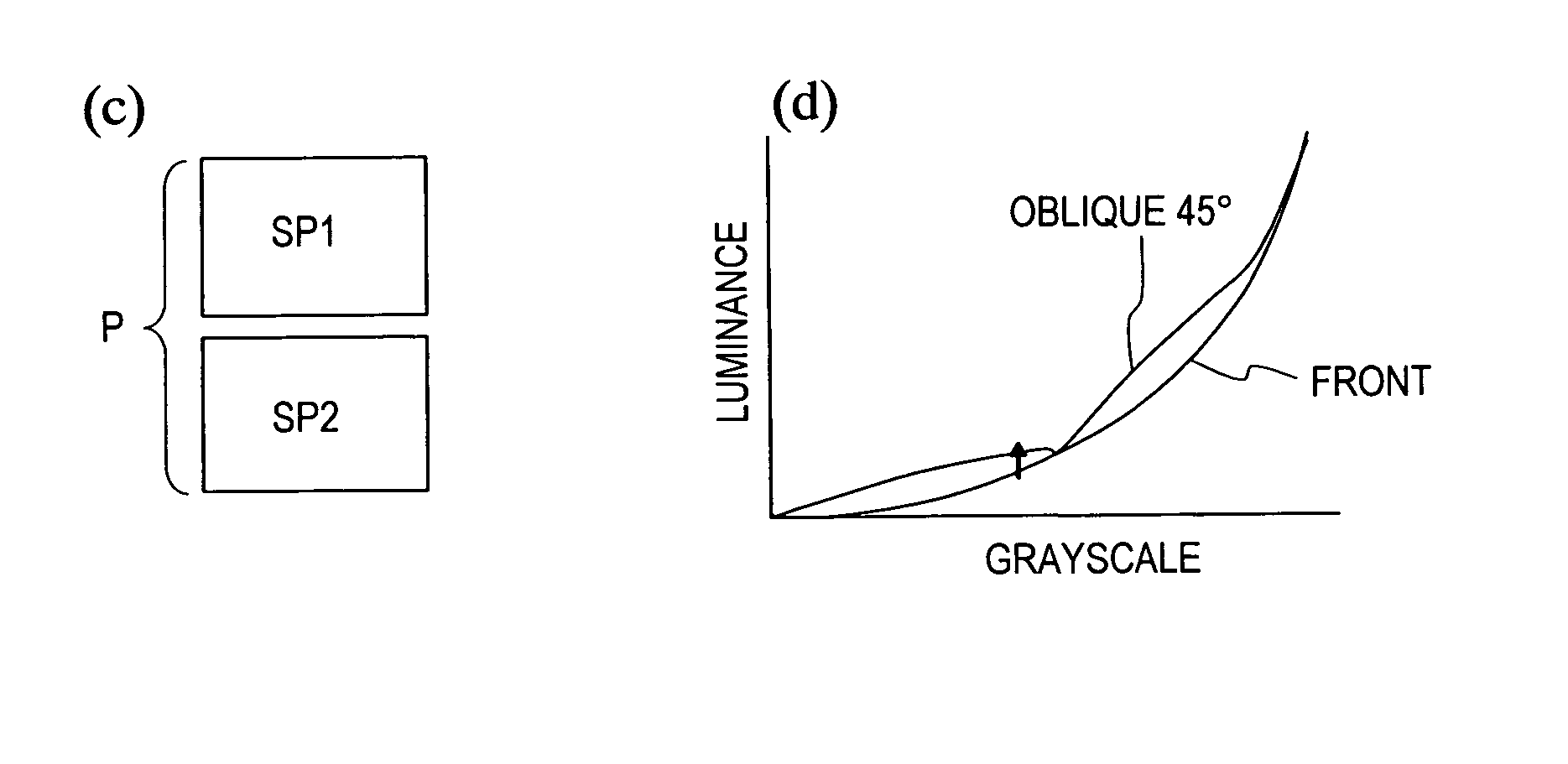
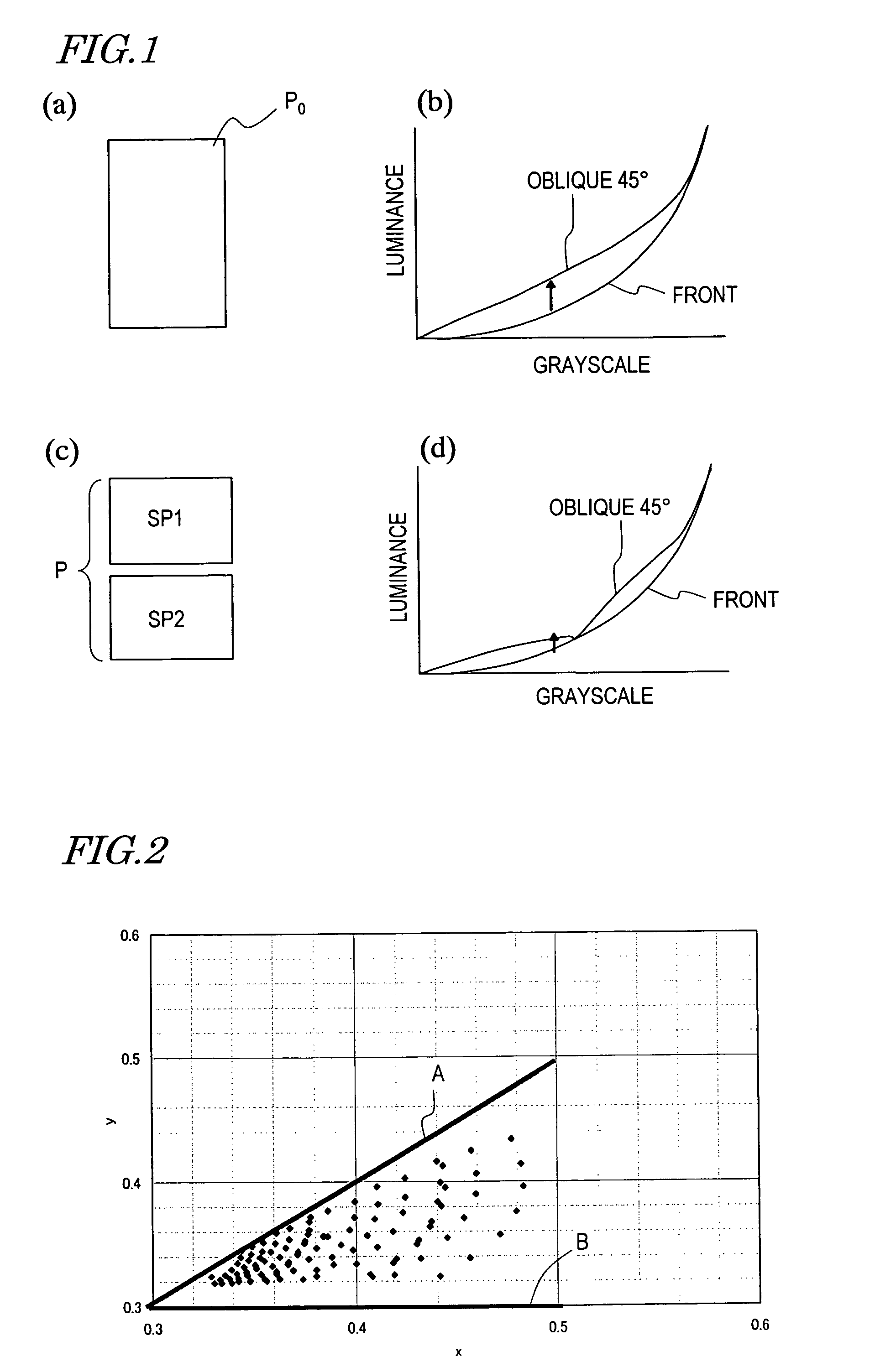
The patent text describes a problem with the viewing angle dependence of the grayscale characteristic (also known as the γ characteristic) of a liquid crystal display device. This problem cannot be completely compensated for even by using the techniques described in previous patents. The text proposes a solution to improve the grayscale characteristic without increasing the number of sub-pixels into which the pixel is divided. The technical effect of this solution is to lower the viewing angle dependence of the grayscale characteristic and improve the display quality of liquid crystal display devices.

Problems solved by technology

One problem unique to liquid crystal display devices is that the display quality varies in accordance with the angle at which the display is observed (viewing angle), namely, that the so-called viewing angle characteristic is lowered.
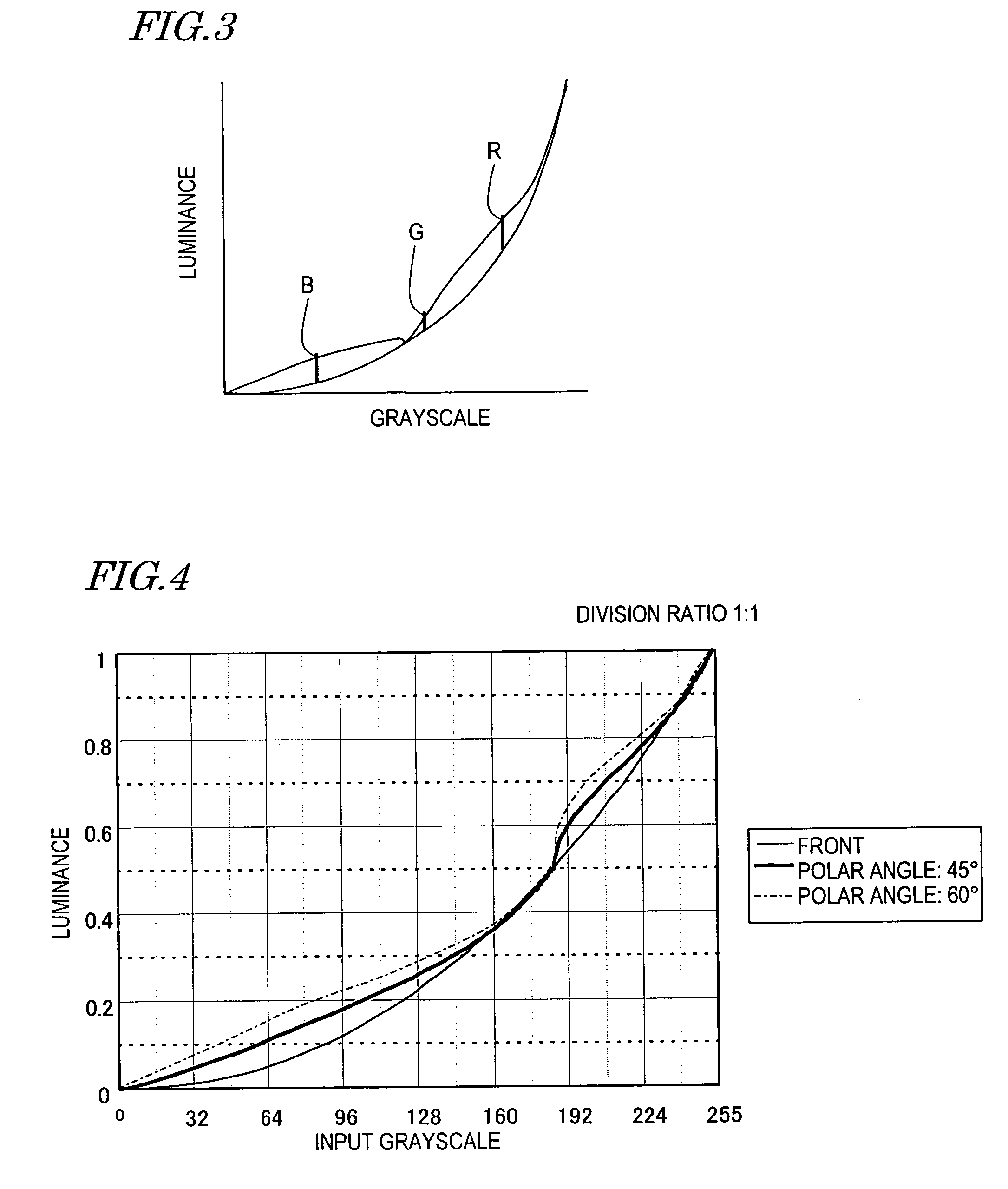
The liquid crystal display devices which are widely used today can display images at a contrast ratio of 10 or greater in a relatively wide viewing angle range, but still have the problem that the grayscale characteristic (γ characteristic) is dependent on the viewing angle.

Method used


Image

  • Liquid crystal display device
  • Liquid crystal display device
  • Liquid crystal display device

Examples


Embodiment Construction

[0041]The present inventors made studies on the improvement of the grayscale characteristic (color reproducibility) while the number of sub-pixels into which one pixel is divided is kept relatively small, e.g., while the number of sub-pixels is the minimum number of 2.

[0042]For the color reproducibility of a display device, memory colors are considered important. In most cases, an image displayed on a display device cannot be directly compared with a subject of display. Therefore, the relationship between the displayed image and the image memorized by the observer is important. For a display device used for TVs, the color of the skin of humans (hereinafter, referred to as the “skin color”) is considered especially important among memory colors (see, for example, Non-patent Document 1).

[0043]FIG. 2 shows a skin color distribution of Japanese men and women in the CIE color system, which is converted from the Muncell color system shown on page 1303 of Non-Patent Document 1. As understo...


PUM


Abstract

A liquid crystal display device includes a plurality of pixels each connected to a signal line via a switching element. Each pixel includes first and second sub-pixels having voltage vs. luminance characteristics different from each other with respect to a signal voltage supplied from the signal line. A threshold signal voltage of the first sub-pixel is lower than that of the second sub-pixel. The pixels form color display pixels which are red, green pixel and blue pixels. Where the area ratio of the first sub-pixel in each of the red, green and blue pixels is SR1, SG1 and SB1, and the ratio of the lighting-up time period of the first sub-pixel of each of the red, green and blue pixels in one vertical scanning period is TR1, TG1 and TB1, the relationship of (SR1×TR1)>(SG1×TG1)>(SB1×TB1) holds.

Description

[0001]This application is the U.S. national phase of International Application No. PCT / JP2006 / 318741, filed 21 Sep. 2006, which designated the U.S. and claims priority to Japanese Patent Application No. 2005-276419, filed 22 Sep. 2005, the entire contents of each of which are hereby incorporated by reference.TECHNICAL FIELD[0002]The present invention relates to a liquid crystal display device, and specifically to a color liquid crystal display device.BACKGROUND ART[0003]Liquid crystal display devices have recently been improved in the display quality and are now widely used for TVs, but are still strongly desired to be further improved in the display quality.[0004]One problem unique to liquid crystal display devices is that the display quality varies in accordance with the angle at which the display is observed (viewing angle), namely, that the so-called viewing angle characteristic is lowered. In conventional TN mode liquid crystal display devices, the grayscale is occasionally inv...

Claims


Application Information

Patent Timeline
Patent Type & Authority Patents(United States)
IPC IPC(8): G09G3/36
CPCG09G3/3648G02F1/133G02F2203/30G09G2300/0452G09G2320/028
Inventor NARUSE, YOHICHIOCHI, TAKASHIKUBO, MASUMIYAMAMOTO, AKIHIRO
Owner SHARP KK
Learn More