Image sensing apparatus and control method for the image sensing apparatus

a control method and image sensing technology, applied in the field control method of image sensing apparatus, can solve the problems of defective pixels during the manufacture of image sensors, deterioration of image quality, and loss of image quality, so as to reduce the time required for detecting pixels and improve the detection accuracy of pixels

Inactive Publication Date: 2012-04-17
CANON KK
View PDF6 Cites 51 Cited by
  • Summary
  • Abstract
  • Description
  • Claims
  • Application Information

AI Technical Summary

Benefits of technology

[0009]The present invention is directed to improving the detection accuracy of pixels including flicker defects and reducing time required to detect pixels including flicker defects.
[0012]According to an exemplary embodiment of the present invention, the detection accuracy in detecting pixels including flicker defects can be improved, and time required to detect pixels including flicker defects can be reduced.

Problems solved by technology

If image signals output from pixels include a great amount of dark current components, the quality of an image formed by the image signals deteriorates.
Even if defective pixels occur at such a level that several pixels are defective in the entire pixel array of the image sensor, the quality of an image obtained by signals from the pixel array is noticeably impaired.
It is considered that defective pixels occur during the manufacture of an image sensor, or after manufacturing, due to radiation of high-energy electromagnetic waves, such as cosmic rays.
Meanwhile, there are also defective pixels at which the signal level of the read signal is either high at one time or low at another time if the signal is read a number of times under the same conditions (same temperature and same accumulation time under the light shielding condition) as when the pixel was detected as a defective pixel.
However, with a method discussed in Japanese Patent Application Laid-Open No. 2003-37781, because image signals of a plurality of frames are acquired, it is necessary to perform a lengthy process of detecting a pixel having a flicker defect and interpolating a signal of the defective pixel (a defective pixel adjusting process).
Consequently, the takt time in a camera manufacturing process (the defective pixel adjusting process) may be prolonged, thus increasing production cost.

Method used


Image

  • Image sensing apparatus and control method for the image sensing apparatus
  • Image sensing apparatus and control method for the image sensing apparatus
  • Image sensing apparatus and control method for the image sensing apparatus

Examples


Embodiment Construction

[0029]Various exemplary embodiments, features, and aspects of the invention will be described in detail below with reference to the drawings.

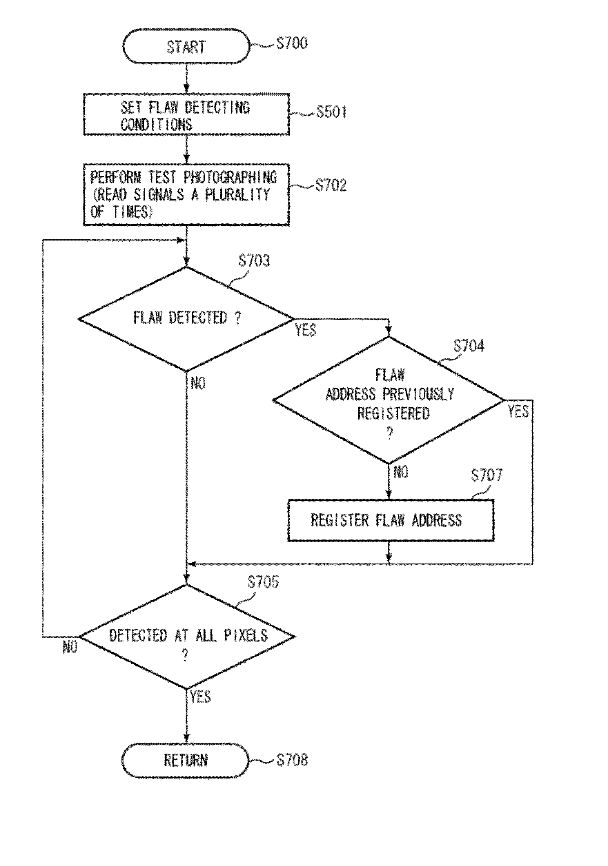
[0030]Defects that occur in digital cameras can be roughly divided into two types. One type is an inherent defect, which originates in structural defects formed in the manufacture of image sensors. The other type is an acquired defect, which is caused by partial destruction of the image sensors mounted in digital cameras due to radiation of high-energy electromagnetic waves, such as cosmic rays.

[0031]Inherent defects can be detected in a defect adjustment step in the manufacturing process of digital cameras. On the other hand, acquired defects can be detected by providing the digital camera with an “automatic adjustment function” for automatic detection of defects during use of a digital camera. This function is activated periodically at timing that does not inhibit the user in using the camera (at startup time or when the power is turned off)....


PUM


Abstract

An image sensing apparatus includes an image sensor including a pixel array, on which a plurality of pixels are arranged, and a reading section configured to read a signal from the pixel array, a detection unit configured to detect a defective pixel in the pixel array based on a signal read from the pixel array by the reading section under a condition that the pixel array is shielded from light, and a control unit configured to control the reading section to read a signal from the pixel array under a condition that a defect tends to occur when the detection unit detects the defective pixel.

Description

BACKGROUND OF THE INVENTION[0001]1. Field of the Invention[0002]The present invention relates to an image sensing apparatus and a control method for the image sensing apparatus.[0003]2. Description of the Related Art[0004]In image sensing apparatuses, such as digital cameras, image sensors, such as charged-coupled device (CCD) sensors, are often used. In the image sensors, dark current components may be contained in image signals output from a pixel array, in which a plurality of pixels are arranged. If image signals output from pixels include a great amount of dark current components, the quality of an image formed by the image signals deteriorates.[0005]In the pixel array of the image sensor, any pixel that outputs a signal which includes a considerable amount of dark current components is referred to as a defective pixel. Even if defective pixels occur at such a level that several pixels are defective in the entire pixel array of the image sensor, the quality of an image obtained...

Claims


Application Information

Patent Timeline
Patent Type & Authority Patents(United States)
IPC IPC(8): H04N9/64H04N5/335H04N5/367H04N5/372
CPCH04N5/367H04N25/68
Inventor NEGISHI, NORIO
Owner CANON KK
Why Eureka
Try Eureka