
System and method for effective mail transmission

a mail transmission system and mail transmission technology, applied in the field of mail transmission systems, can solve the problems of not being able to ignore, a lot of e-mails, and a lot of processes that can be performed in parallel, and achieve the effect of efficient transmission

Active Publication Date: 2012-04-17
SNAPCHAT
View PDF24 Cites 238 Cited by
  • Summary
  • Abstract
  • Description
  • Claims
  • Application Information

AI Technical Summary

Benefits of technology

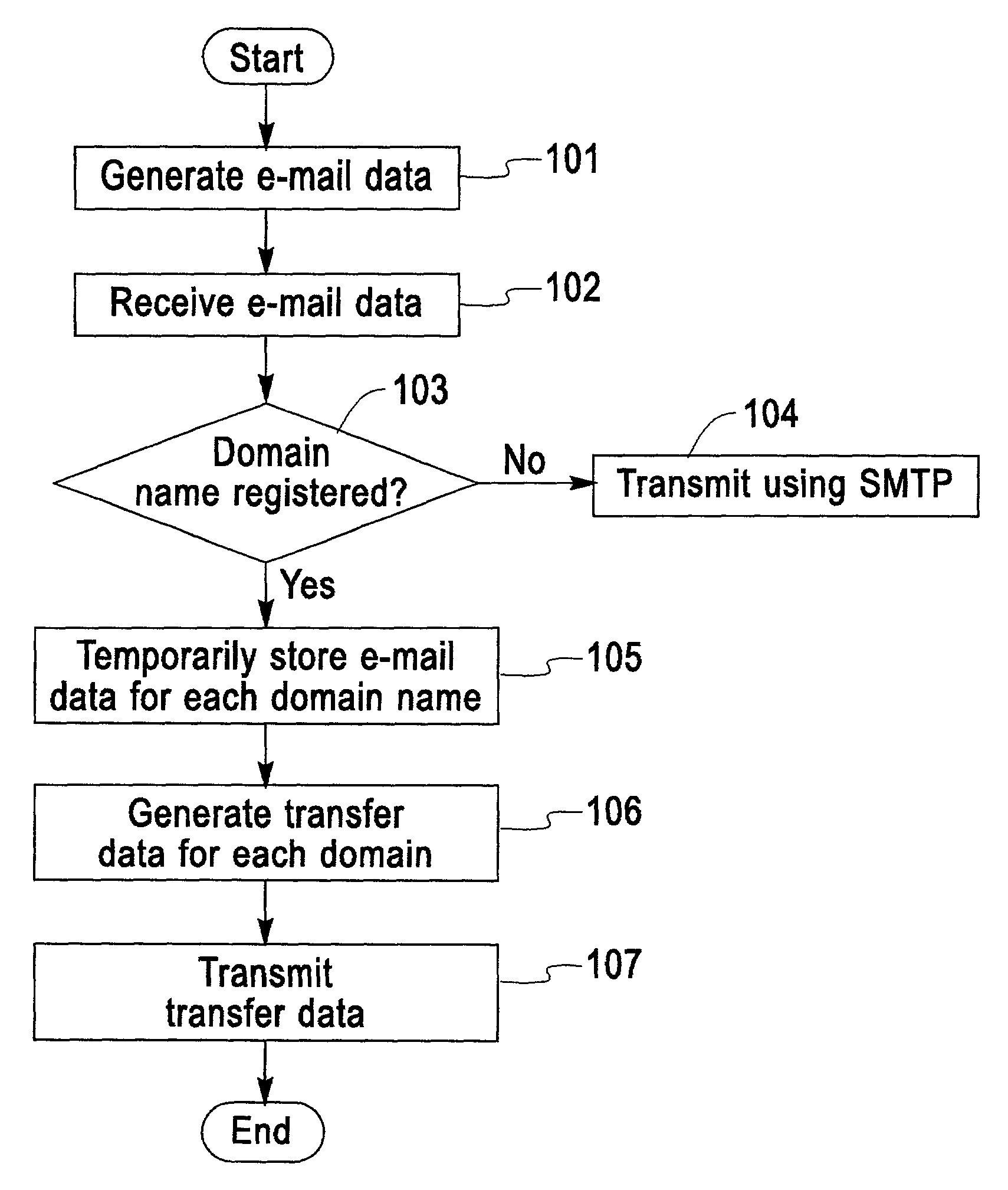
[0019]Specifically, according to the present invention, a mail transmission system receives e-mail data, which includes destination address information and mail text information constituted by a mail text and a subject name, and sorts the e-mail based on server domain information that is included in the destination address information. As for the sorting results, multiple sets of the e-mail data addressed for multiple recipients in which the server domain information is the same (i.e., the mail server is the same) are grouped, and the transmission data is generated. The generated transmission data is transmitted via a network to a server designated by the server domain information. In this manner, based on the server domain information included in the destination address information, the server of the sender groups and transmits the e-mail data for each server, such as an each ISP server, that the recipient uses. Therefore, the e-mail data (transmission data) can be efficiently transmitted from the mail transmission system (server) of the sender to the server, such as the ISP server. It is especially preferable that, instead of SMTP, FTP (File Transfer Protocol) or HTTP (Hypertext Transfer Protocol) be employed between the mail transmission system of the sender and the server of the recipient.

Problems solved by technology

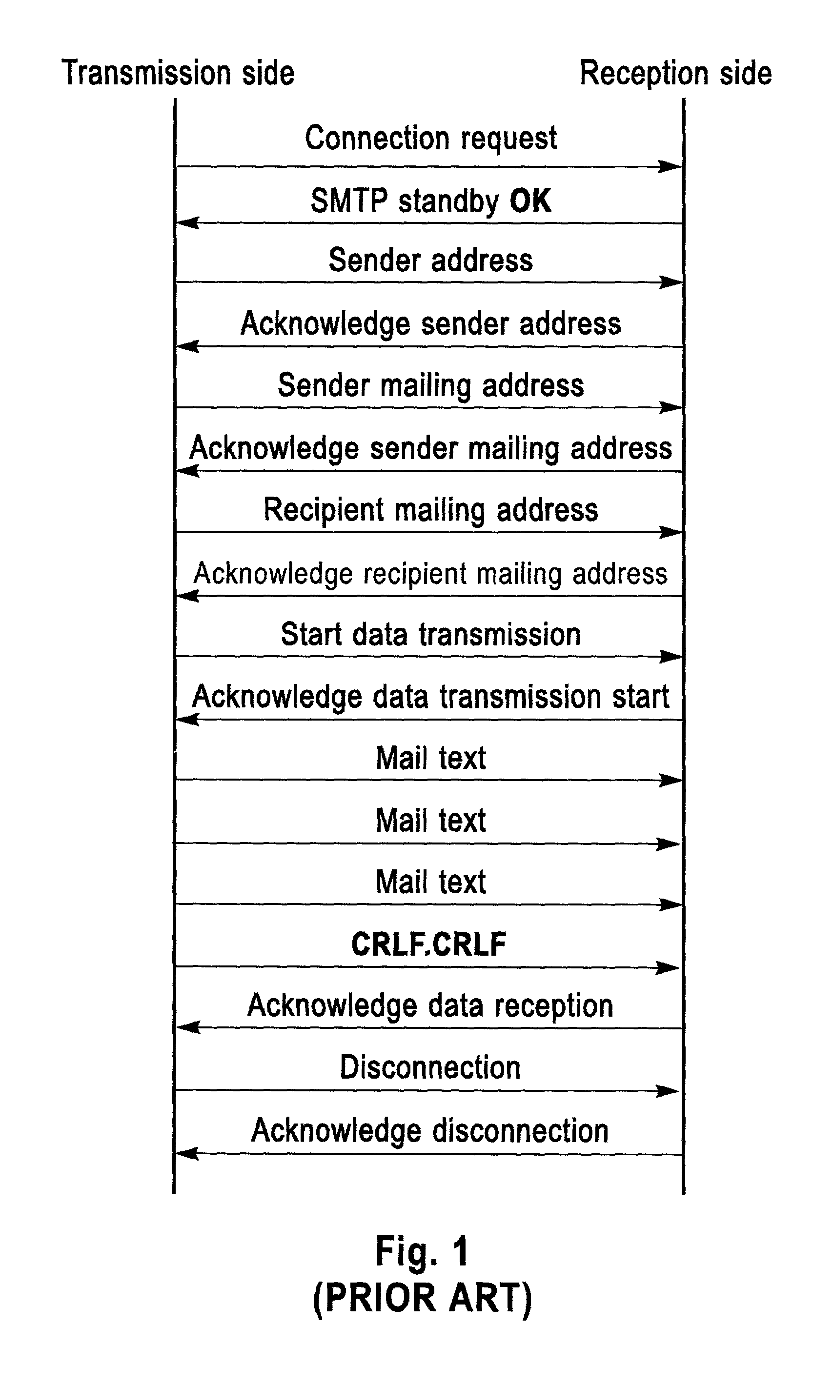
However, when this conventional technique is used, the following problems are encountered.
Since there is a hardware restriction on this process, the number of processes that can be performed in parallel is limited.
While no critical problem is encountered so long as the volume of the e-mail transmitted is small, transmitting a lot of e-mails, for example, several hundred thousand e-mails, takes a great deal of time.
Therefore, since a load is thereby imposed on the entire Internet, the above described problem becomes even more critical and can not be ignored.
As is described above, for the transfer of a large volume of e-mail, data transfer among mail servers by SMTP has constituted a bottleneck.
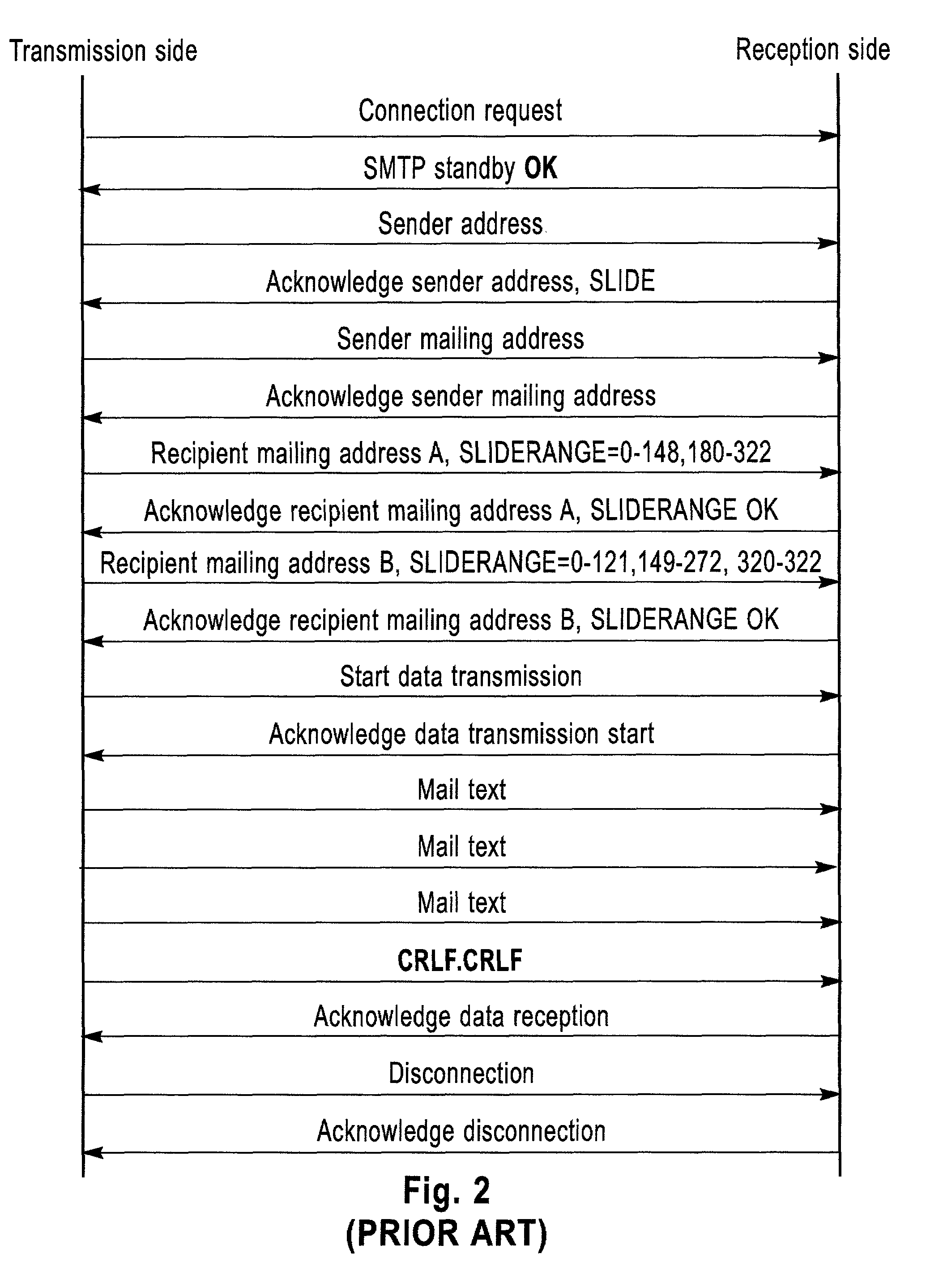
However, so long as SMTP is employed, the protocol in itself requires that multiple servers be used to relay the e-mail data, and as a result, dramatic effects can not always be obtained.
In these cases, the amount of data for the mail text is enormously expanded when a large number of e-mails are to be transmitted, it can be said that no ameliorative effects are obtained.
And for the above described reasons, the current technique cannot cope with this request.

Method used


Image

  • System and method for effective mail transmission
  • System and method for effective mail transmission
  • System and method for effective mail transmission

Examples


first embodiment

1. First Embodiment

[0044]FIG. 3 is a diagram for explaining the configuration of an e-mail transfer system according to a first embodiment of the present invention. According to the e-mail transfer system, when an information sender, such as a bank or a stock brokerage, desires to transmit multiple e-mails through a server 10 (a mail transmission system or a transmission server), the server 10 collates data of these e-mails for each distributor, such as an ISP, and transmits the data to a server 30 (a reception server) of the distributor via a network 20 such as the Internet. The server 30 of the distributor analyzes the collated data, generates multiple e-mails and distributes the e-mails to the destinations (clients) specified by the mailing addresses.

[0045]In this embodiment, the e-mail transfer system is employed by a bank or a stock brokerage to notify their client (an e-mail recipient), using an e-mail, that the rate of the brand of a derivative, such as a foreign currency or ...

second embodiment

2. Second Embodiment

[0071]An e-mail transfer system according to a second embodiment of the present invention that uses a template to prepare e-mail will now be described. In the following explanation, the same reference numerals as used for the first embodiment are again used to denote corresponding components, and no further explanation for them will be given.

[0072]In this embodiment, as in the first embodiment, when an information sender, such as a bank or a stock brokerage, transmits multiple e-mails using a server 10, the e-mail transfer system groups the data for these e-mails for each distributor, such as an ISP, and transmits the data via a network 20, such as the Internet, to a server 30 of a distributor. The distributor's server 30 then analyzes the grouped data to generate multiple e-mails, and distributes the thus obtained e-mails to the destinations (clients) having the corresponding mailing addresses A.

[0073]As is shown in FIG. 10, the server 10 of the sender can be co...


PUM


Abstract

A system and method for rapidly transmitting a large volume of e-mails. Based on domain names obtained from destination mailing addresses, a server 10 for a sender sorts e-mails to be transmitted, generates transfer data for each domain name by grouping e-mail data, and uses FTP to transmit the transfer data to servers 30 for distributors whose domain names correspond to those for which the transfer data were generated. At this time, compression is effective for improving the transmission of the transfer data. The server 30, upon receiving transfer data, analyzes the received transfer data to obtain the data for individual e-mails, and distributes the e-mail data to the mail boxes of individual recipients.

Description

BACKGROUND OF THE INVENTION[0001]1. Field of the Invention[0002]The present invention generally relates to methods and systems for mail transmission. Specifically, the invention provides a mechanism especially appropriate for the transfer of a great number of e-mails addressed to multiple recipients.[0003]2. Description of the Related Art[0004]As the use of e-mail has spread explosively, senders, including a variety of different companies, have come to rely on it for the dissemination of topical product and service information for clients. For example, manufacturers use e-mail to advertise new products, while banks and stock brokerages employ it for the distribution of stock exchange and stock price information. In general, information distribution services are on the increase, and even today, there are some companies that distribute relevant information to several hundreds of thousands of clients.[0005]As is well known, when preparing to dispatch an e-mail, a sender creates e-mail ...

Claims


Application Information

Patent Timeline
Patent Type & Authority Patents(United States)
IPC IPC(8): G06F15/16G06F13/00H04L12/58
CPCH04L51/14H04L51/214
Inventor YAMAMOTO, GAKU
Owner SNAPCHAT
Learn More