Splashguard for high flow vacuum bubbler vessel

a vacuum bubbler and high-flow technology, which is applied in the direction of liquid handling, liquid degasification, separation processes, etc., can solve the problem of not being able to have the chemical precursor leave the container through the outlet in liquid form, and achieve the effect of minimizing liquid droplets

Active Publication Date: 2012-04-24
VERSUM MATERIALS US LLC
View PDF19 Cites 10 Cited by
  • Summary
  • Abstract
  • Description
  • Claims
  • Application Information

AI Technical Summary

Benefits of technology

[0005]The present invention is a container having a diptube inlet ending proximate a base of the container; at least one baffle disc positioned between the outlet of the diptube and an outlet of the container, configured to provide a narrow annular space between the baffle disc and an inner surface of a sidewall of the container; and an annular, radially inward projecting deflector ledge on the sidewall, proximate the baffle disc; the baffle disc and deflector ledge capable of minimizing liquid droplets from entering the outlet to the container.

Problems solved by technology

It is undesirable to have the chemical precursor leave the container through the outlet in the liquid form, even as small droplets.

Method used


Image

  • Splashguard for high flow vacuum bubbler vessel
  • Splashguard for high flow vacuum bubbler vessel
  • Splashguard for high flow vacuum bubbler vessel

Examples


Embodiment Construction

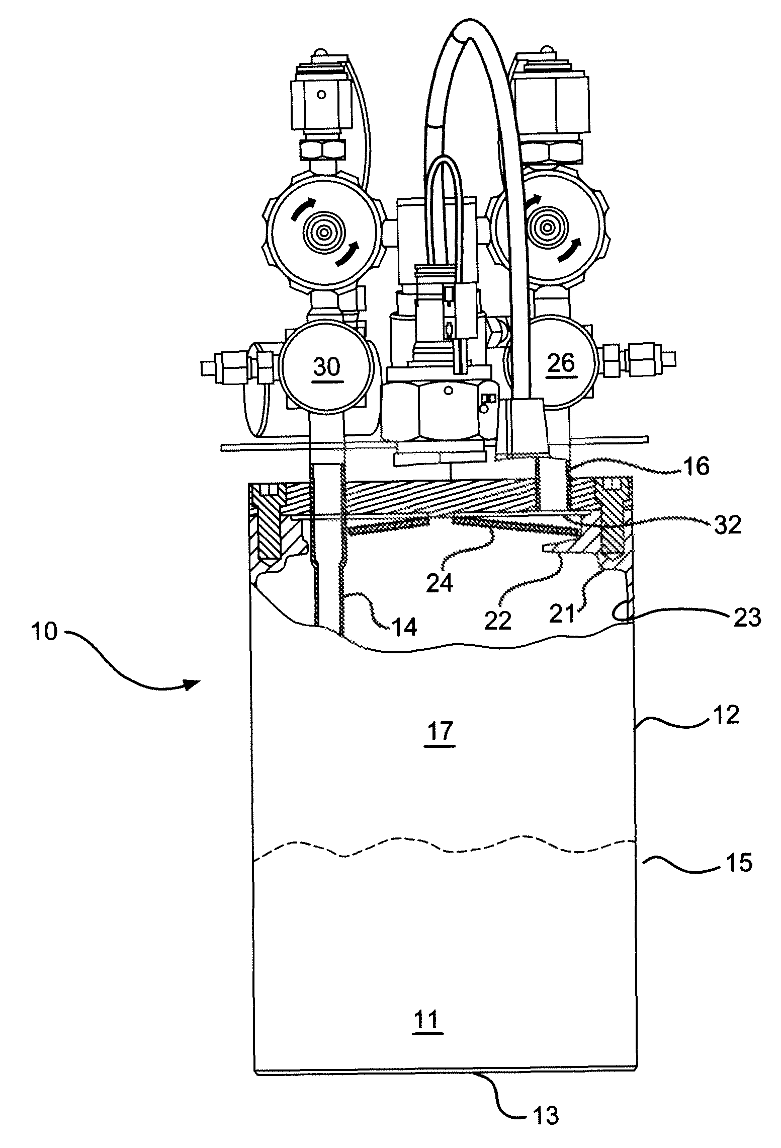
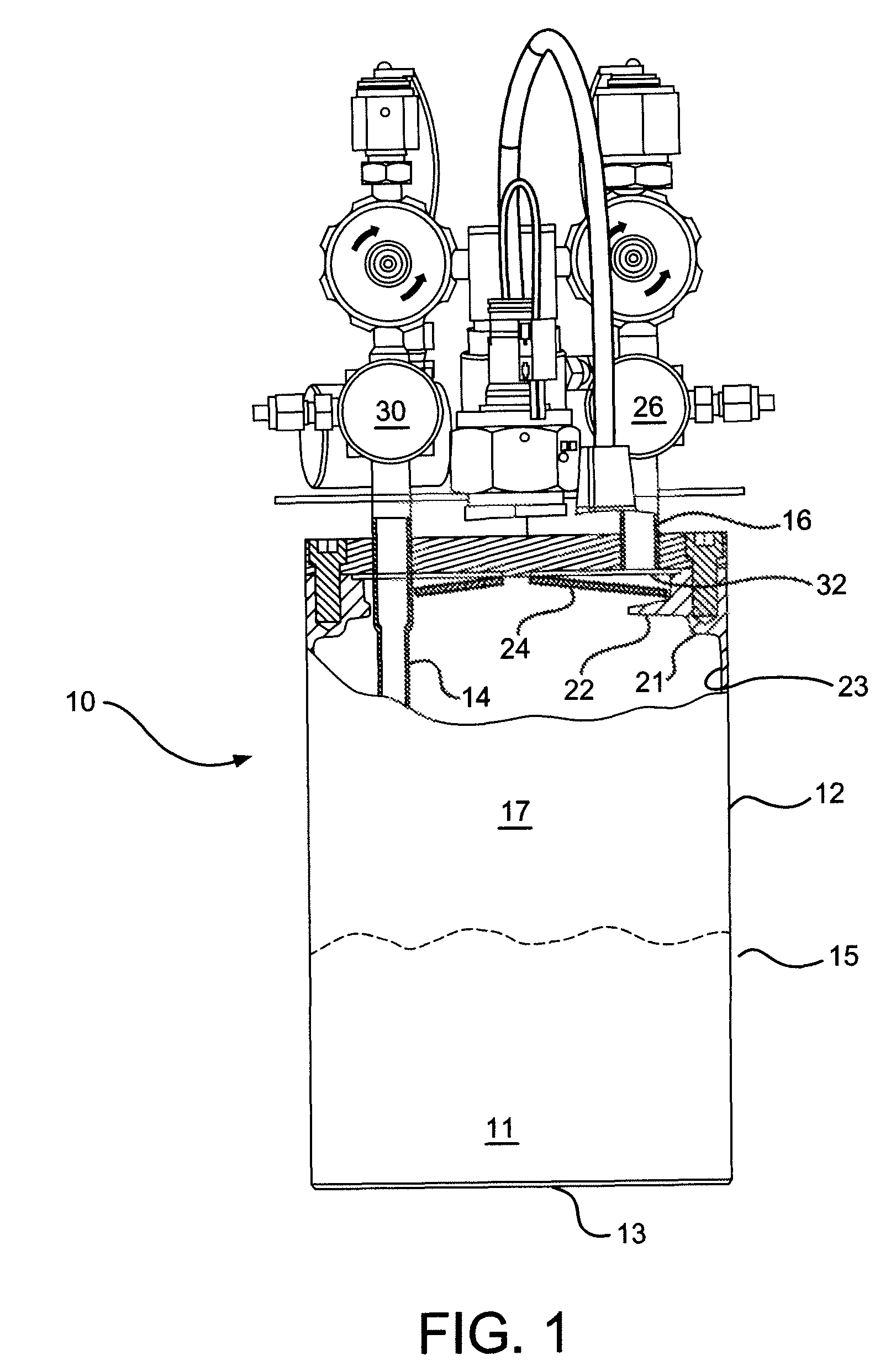
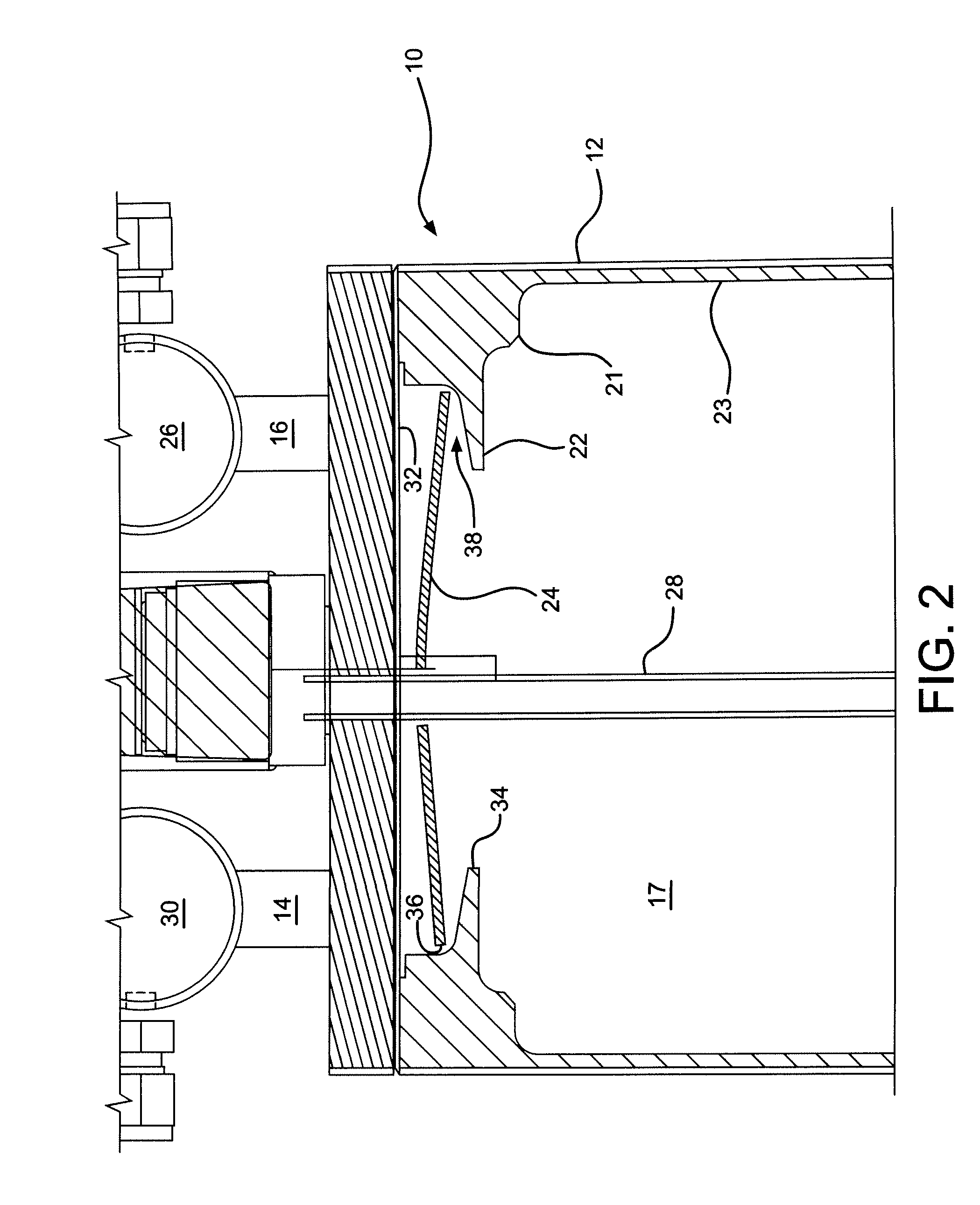
[0012]The present invention is a vapor generation bubbler container designed for service in high vacuum or high flowrate conditions. The design prevents splashing and transport of aerosol droplets into the outlet delivery line that would result in erratic chemical mass flow delivery.

[0013]Semiconductor manufacturers are turning to the use of high value chemicals that are increasingly difficult to transport for deposition onto a wafer in a vacuum chamber or tool. The bubbler container of the present invention allows liquid chemical to be delivered from the container as a vapor at high vacuum, without the splashing and the formation of aerosol droplets in the outlet of the container that result in erratic chemical mass delivery rate. The present invention has a lower surface design that enables a constant saturation of a carrier gas with chemical vapor down to very low levels of the residual chemical. Yet, the present invention prevents splashing and the formation of aerosol droplets ...


PUM

PropertyMeasurementUnit
volumeaaaaaaaaaa
homogenousaaaaaaaaaa
pressureaaaaaaaaaa

Abstract

The present invention is a container having a diptube inlet, at least one baffle disc positioned between the outlet of the diptube and the outlet of the container to provide a narrow annular space between the baffle disc and the sidewall of the container to prevent liquid droplets from entering the outlet to the container and the inner surface of the container sidewall and an annular, radially inward projecting deflector ledge on the sidewall, proximate the baffle disc. The present invention is also a process of delivering a chemical precursor from a container having the above structure. Liquid and vapor delivery are both contemplated.

Description

BACKGROUND OF THE INVENTION[0001]The electronics fabrication industry uses chemical precursor containers that convert liquid chemicals into chemical vapor for delivery to electronics fabrication reactors, i.e. tools, for conducting chemical vapor deposition (“CVD”). CVD is a favored technique for forming layers, films and other depositions in the construction of electronic fabrications such as integrated circuits or computer chips. Liquids or solids are preferred as sources of supply because of the efficiency of transport and storage of a volume of chemical precursor, but the industry frequently prefers to actually deliver the chemical precursor at the site of the tool in the form of a vapor, i.e. CVD. Alternatively, some fabrications are conducted using direct liquid injection (“DLI”), although even then, the liquid is vaporized in the tool after delivery.[0002]When using vapor delivery for CVD, the containers typically have an inert carrier gas passed through them or bubbled, i.e....

Claims


Application Information

Patent Timeline
Patent Type & Authority Patents(United States)
IPC IPC(8): B01F3/04
CPCB01J4/008B01J4/02
Inventor BIRTCHER, CHARLES MICHAELSTEIDL, THOMAS ANDREW
Owner VERSUM MATERIALS US LLC
Why Eureka
Try Eureka