Split flexible tube biasing and directional atherectomy device and method

a flexible tube and stent technology, applied in the field of devices and methods, can solve the problems of stent restnosis, block blood flow, angina, hypertension,

Inactive Publication Date: 2012-04-24
CARDIOVASCULAR SYST INC
View PDF32 Cites 35 Cited by
  • Summary
  • Abstract
  • Description
  • Claims
  • Application Information

AI Technical Summary

Problems solved by technology

If left untreated, this occluding material can cause angina, hypertension, myocardial infarction, strokes and the like.
Studies have shown, however, that a significant percentage of patients who have undergone balloon angioplasty and had a stent placed in an artery experience stent restenosis—i.e., blockage of the stent which most frequently develops over a period of time as a result of excessive growth of scar tissue within the stent.
As the burr is removing stenotic tissue, however, it blocks blood flow.
This construction is limited, however because, as Clement explains at Col. 3, lines 53-55, that the asymmetrical burr is rotated at “lower speeds than are used with high speed ablation devices, to compensate for heat or imbalance.” That is, given both the size and mass of the solid burr, it is infeasible to rotate the burr at the high speeds used during atherectomy procedures, i.e., rotational speeds within the range of about 20,000-200,000 rpm.
Essentially, the center of mass offset from the rotational axis of the drive shaft would result in development of significant and undesirable centrifugal force, exerting too much pressure on the wall of the artery and creating too much heat and excessively large particles.
This flexion allows for a larger diameter opening during high speed operation, but may also provide less control than desired over the diameter of the artery actually abraded.
These pre-curved guide wire designs are not, inter alia, capable of providing a controllable biasing force on one side of the lumen for directional cutting and / or grinding occluding material on the other side of the lumen.
Schnepp-Pesch does not, however, provide directionality of cutting nor does it provide a controllable biasing force on one side of the lumen for directional cutting and / or grinding occluding material on the other side of the lumen.
Goldin does not, however, provide a controllable biasing force on one side of the lumen for directional cutting and / or grinding occluding material on the other side of the lumen.
Selmon's patents do not, however, provide directionality of cutting and / or grinding of occluding material nor do they provide a controllable biasing force on one side of the lumen for directional cutting and / or grinding of occluding material on the other side of the lumen
Patterson's patents do not, however, provide directional cutting and / or grinding nor do they provide a controllable biasing force on one side of the lumen for directionality of cutting and / or grinding on the other side of the lumen

Method used


Image

  • Split flexible tube biasing and directional atherectomy device and method
  • Split flexible tube biasing and directional atherectomy device and method
  • Split flexible tube biasing and directional atherectomy device and method

Examples


Embodiment Construction

[0034]While the invention is amenable to various modifications and alternative forms, specifics thereof are shown by way of example in the drawings and described in detail herein. It should be understood, however, that the intention is not to limit the invention to the particular embodiments described. On the contrary, the intention is to cover all modifications, equivalents, and alternatives falling within the spirit and scope of the invention.

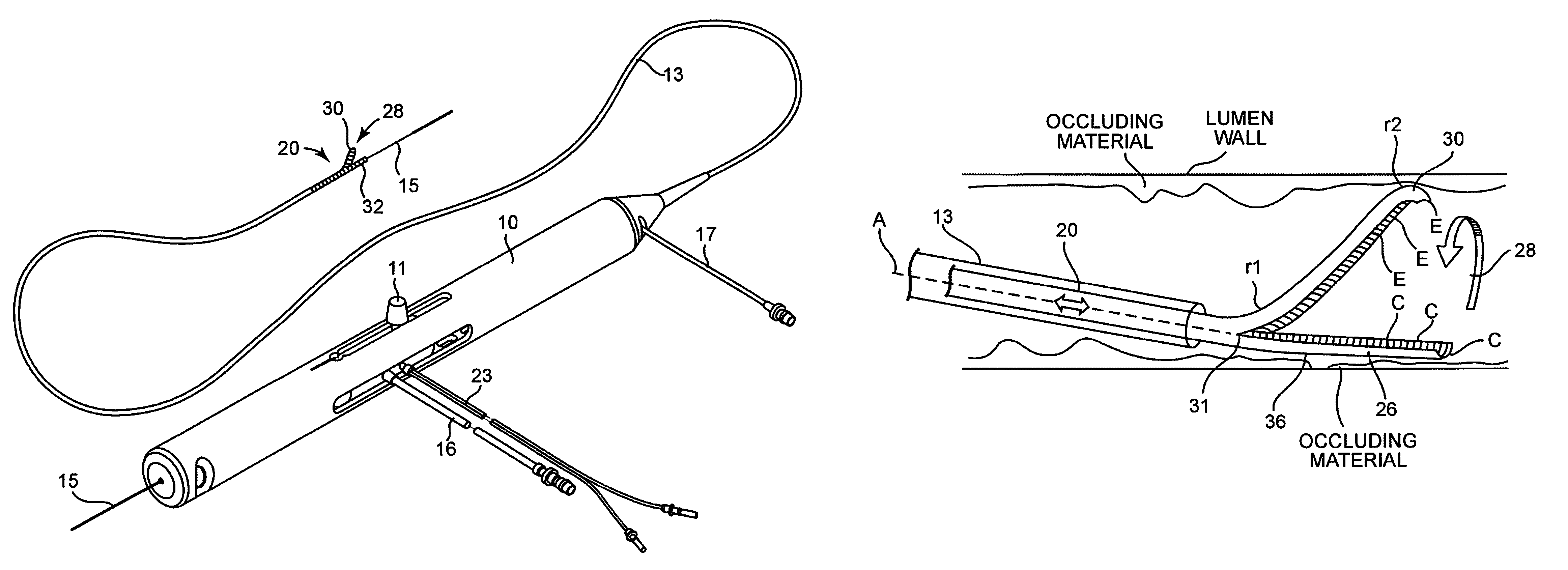
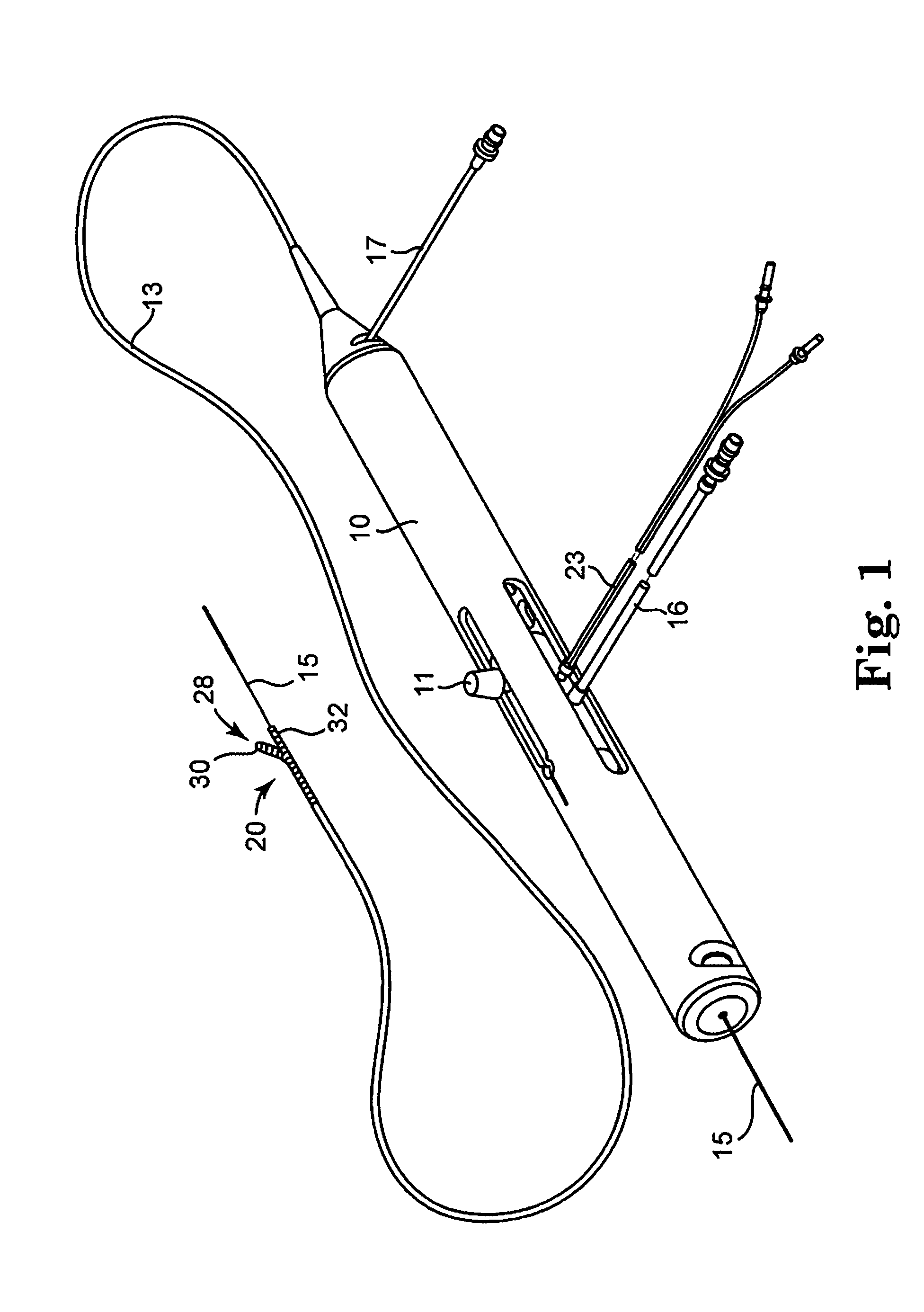
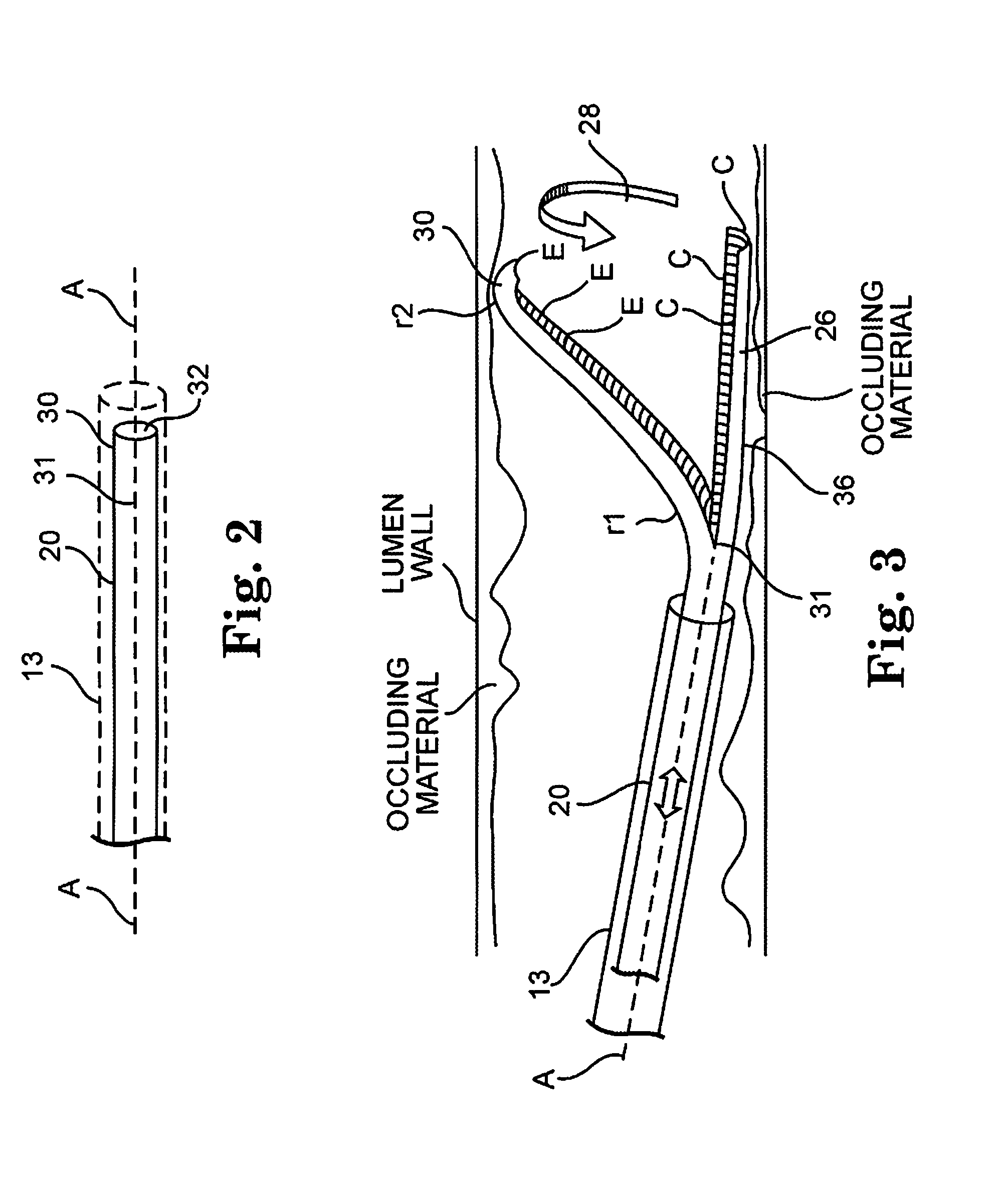
[0035]FIG. 1 illustrates one embodiment of a rotational atherectomy system and device of the present invention. The system includes a handle portion 10, an elongated, flexible catheter tube 20 having an ablating element 28 which further comprises a biasing element 30 and a cutting element 32, the biasing element 30 and the cutting element 32 resulting from, in the illustrated embodiment, a splitting of the flexible catheter tube 20 at its distal end. Flexible catheter tube 20 comprises a lumen with which guide wire 15 may be in operative comm...


PUM


Abstract

The invention provides a rotational atherectomy system, device and method having a flexible, elongated, rotatable catheter tube that is split into two elements, a biasing element and a cutting element, distally and wherein the biasing element and cutting element are capable of forming a first and retracted position for insertion into a lumen and a second and expanded position for ablation. The biasing element is biased in the expanded position, thereby placing a biasing force against the lumen wall and pressing the cutting element against the opposite side of the lumen wall for directional cutting and / or grinding, either by rotation, axial translation, vibration or a combination thereof.

Description

CROSS-REFERENCE TO RELATED APPLICATIONS[0001]The present application claims priority to provisional application No. 61 / 058,983, filed on Jun. 5, 2008 under the title, “SPLIT FLEXIBLE TUBE DIRECTIONAL LARGE VESSEL ATHERECTOMY DEVICE”, the contents of which are incorporated by reference herein.BACKGROUND OF THE INVENTION[0002]1. Field of the Invention[0003]The invention relates to devices and methods for removing tissue from body passageways, such as removal of atherosclerotic plaque from arteries, utilizing a rotational atherectomy device.[0004]2. Description of the Related Art[0005]A variety of techniques and instruments have been developed for use in the removal or repair of tissue in arteries and similar body passageways. A frequent objective of such techniques and instruments is the removal of atherosclerotic plaques in a patient's arteries. Atherosclerosis is characterized by the buildup of fatty deposits (atheromas) in the intimal layer (under the endothelium) of a patient's bl...

Claims


Application Information

Patent Timeline
Patent Type & Authority Patents(United States)
IPC IPC(8): A61B17/22
CPCA61B17/320758A61B17/320725A61B2017/00867A61B2017/320733
Inventor PIIPPO, CASSANDRA A.DARLEY, JESSE C.
Owner CARDIOVASCULAR SYST INC
Why Eureka
Try Eureka