
Sound suppressor

a technology of sound suppressor and suppressor, which is applied in the direction of weapons, weapon components, etc., can solve the problems of giving up much of their kinetic energy before they exit, and achieve the effects of suppressing sound and flash, reducing flash, and giving up much of their kinetic energy

Active Publication Date: 2012-05-01
FN AMERICA +1
View PDF52 Cites 72 Cited by
  • Summary
  • Abstract
  • Description
  • Claims
  • Application Information

AI Technical Summary

Benefits of technology

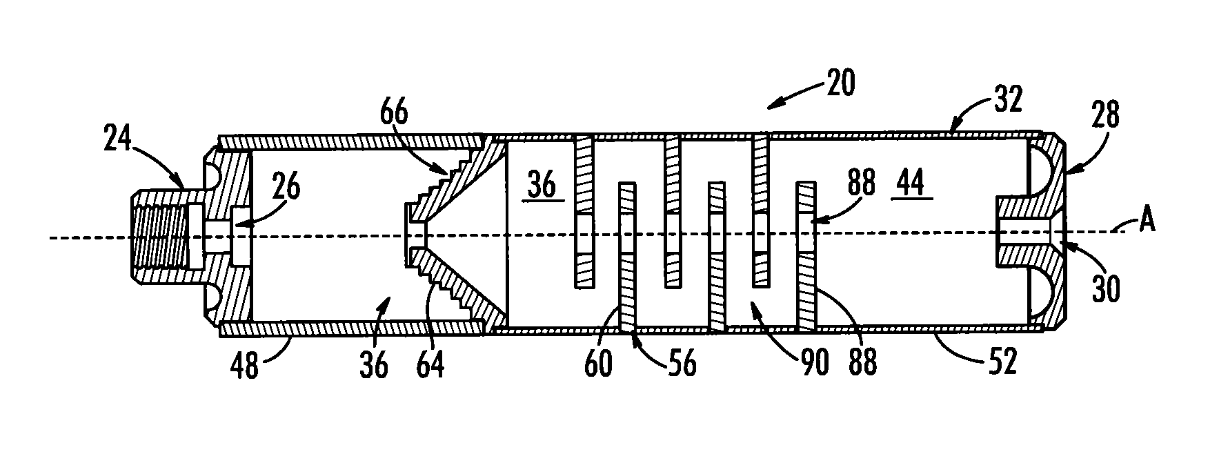
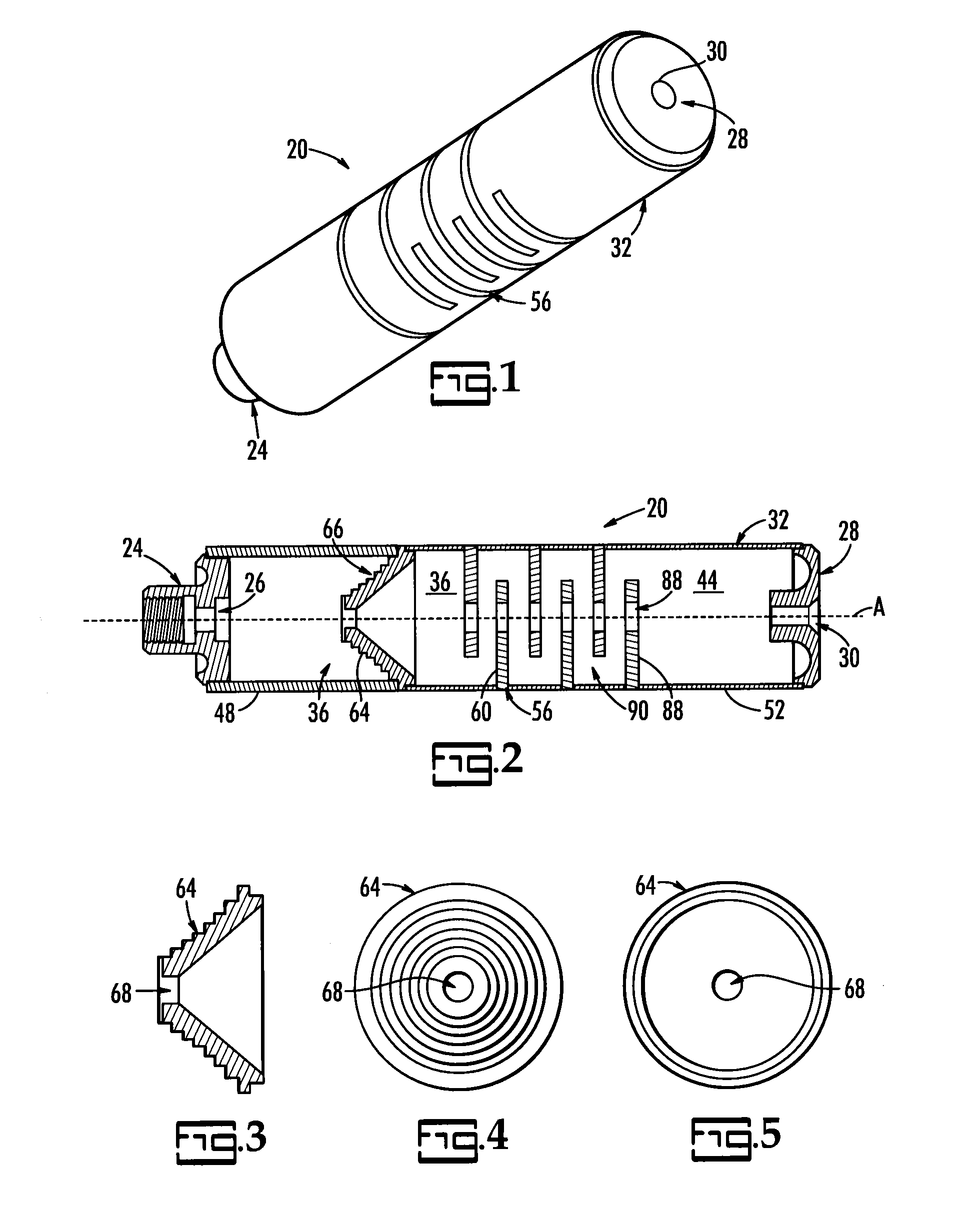
[0009]The present device suppresses sound and flash by creating interacting paths of combustion gas. In particular, while a first portion of the gas follows the bullet along a first path through the suppressor, a second portion of the gas is diverted from the first path radially to a second path and then is repeatedly made to cross the first path by a series of baffles so that the two portions of gas interfere with each other turbulently, and therefore quickly give up much of their kinetic energy before they exit the suppressor. Preferably, the baffles defining the second path are such as to impart a flow to the second portion of gas to cause the present suppressor to flush itself of carbon and metal particles. It is believed that the interaction of the two paths also accelerates completion of combustion of the gas so as to reduce flash.
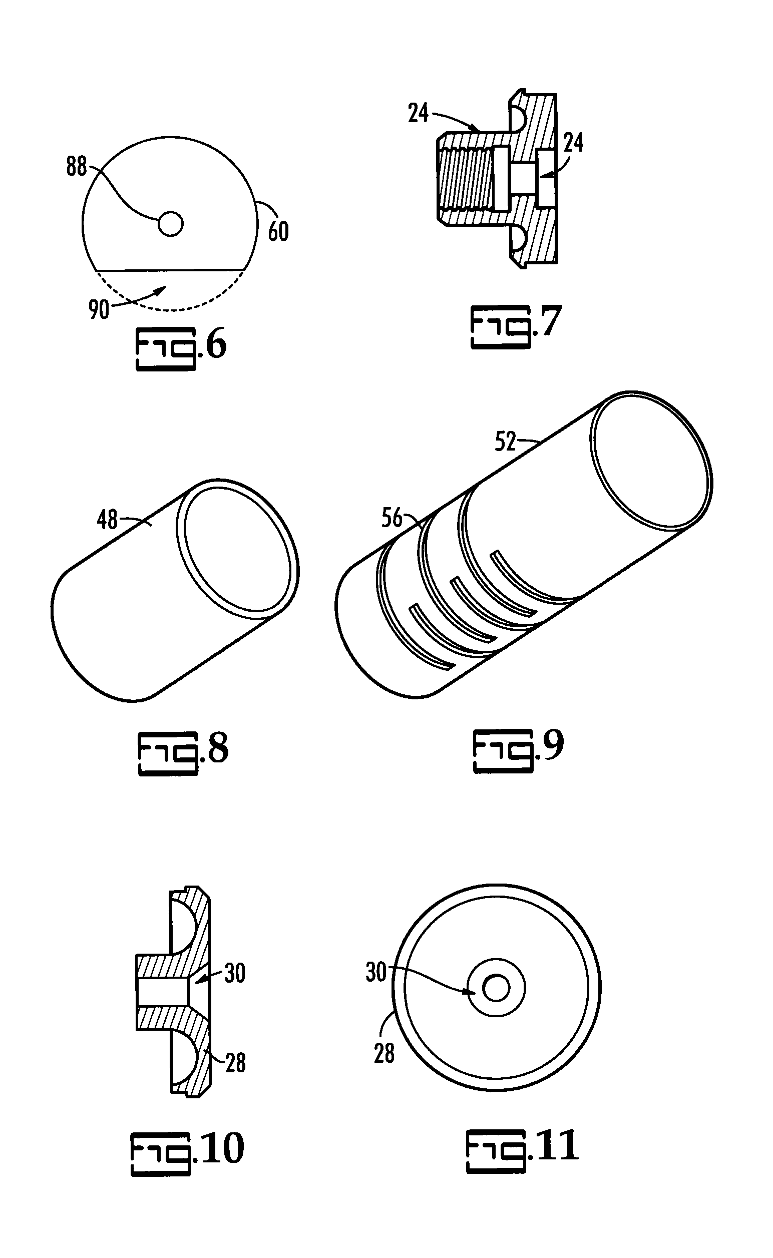
[0010]The present suppressor includes a series of baffles having a central hole for the first path and a radial passage that may be a hole or a cutaway portion of the baffle. Each baffle is attached to the suppressor housing through a slot formed in that housing at the appropriate axial and azimuthal location where it can be secured to the housing accurately and easily. The number of baffles, their spacing, and their orientation with respect to each other has an impact on the suppression of sound of the suppressor. The use of slots in the housing to facilitate installation of the baffles and their securement to the housing is a feature of the present suppressor.
[0011]A feature of the present suppressor is the use of a series of baffles that have passages formed therein to define the second, serpentine path that crosses the first path repeatedly. This feature makes it possible to use the second portion of the gas to slow the first portion. The sequence of baffles also acts like a heat exchanger, picking heat up from the turbulent gas as the gas slows and cools while transmitting that heat to the baffles and the wall of the suppressor.
[0012]Another feature of the present suppressor is the use of baffles to create a self-cleaning swirl of gas within the chamber. The self-cleaning prevents build up of deposits and enables the suppressor to shed heat better and thereby operate effectively longer.

Problems solved by technology

In particular, while a first portion of the gas follows the bullet along a first path through the suppressor, a second portion of the gas is diverted from the first path radially to a second path and then is repeatedly made to cross the first path by a series of baffles so that the two portions of gas interfere with each other turbulently, and therefore quickly give up much of their kinetic energy before they exit the suppressor.

Method used


Image

  • Sound suppressor
  • Sound suppressor
  • Sound suppressor

Examples


Embodiment Construction

[0025]The present invention is a sound suppressor for use with a firearm and a method for making same.

[0026]Referring now to FIGS. 1 and 2, there is shown a sound suppressor, generally indicated by reference number 20, shown in a perspective exterior view in FIG. 1 and in cross-section from the side in FIG. 2. Suppressor 20 includes a muzzle fitting 24 with nozzle 26 at one end and an end cap 28 with beveled end 30 at the opposing end of a two-part cylindrical housing 32. Muzzle fitting 24 is adapted to be threaded to the end of a barrel of a firearm (not shown) and may be formed as nozzle 26 toward the interior chamber of a first housing segment 48 so as to contribute to the radial dispersion of combustion gases into the chamber of first housing segment 48. If the barrel has a flash hider on the end or other fitting or coupling, muzzle fitting 24 may be modified to attach to such flash hider, fitting or coupling. It is sufficient that muzzle fitting 24 be dimensioned to fit to the ...


PUM


Abstract

A sound suppressor suppresses sound and flash by creating interacting paths of gas. While a first portion of the gas follows a first path through the suppressor, a second portion of the gas is diverted radially from the first path to a second path and then repeatedly made to cross the first path by a series of baffles with alternating radial passages so that the two portions of gas interfere and interact with each other, and therefore quickly give up much of their kinetic energy before they exit the suppressor. Preferably, the baffles defining the second path impart a swirl to the second portion of gas to cause the present suppressor to flush itself of carbon and metal particles. The interaction of the two portions also accelerates completion of combustion of the gas to thereby reduce flash.

Description

PRIORITY CLAIM[0001]Claim is made to the priority benefit of U.S. provisional patent application Ser. No. 61 / 309,041 filed Mar. 1, 2010, which application is incorporated herein in its entirety by reference.BACKGROUND OF THE INVENTION[0002]When a firearm is fired, the burning of the powder charge in the metal shell casing provides the pressure force to accelerate the bullet through the barrel. From there, the bullet's kinetic energy speeds it on toward its target. The burning of the charge generates gaseous by-products that not only accelerate the bullet but also carry small particles of unburned powder and metal from the shell casing / bullet. These follow the bullet down the barrel and out the muzzle where, no longer confined, they disperse quickly.[0003]The sound of the firing of the round and the flash of still-burning power at the muzzle give away the information that a firearm has been fired and where that firearm is located. Conversely, reducing the sound and suppressing the fl...

Claims


Application Information

Patent Timeline
IPC IPC(8): F41A21/30
CPCF41A21/30
Inventor MOORE, CHARLES
Owner FN AMERICA
Learn More