Pylon caisson attachment on a wing, gripping a lateral panel of the caisson

a technology of lateral panel and wing, which is applied in the field of wing attachment of pylon caisson, can solve the problems of significant mass gain, and achieve the effects of increasing the pitch centre, increasing the lateral distance, and increasing the width of the wing

Active Publication Date: 2012-05-01
AIRBUS OPERATIONS (SAS)
View PDF7 Cites 2 Cited by
  • Summary
  • Abstract
  • Description
  • Claims
  • Application Information

AI Technical Summary

Benefits of technology

[0015]So, by placing one of the two first front attachment fittings externally relative to the associated lateral panel, and therefore externally relative to the caisson, the advantageous result is an increase in the lateral distance of the two front attachments, without as such generating an increase in the width of this caisson. As a consequence, the original solution retained ensures absorbing of the substantial forces transiting between the pylon and its corresponding wing element, and in particular that of the vertical forces associated with absorbing the torque exerted according to the longitudinal axis of the pylon, without generating aerodynamic penalties. Also, the increase of the pitch centre between the two front attachments also reduces the sizing of these attachments before absorbing less substantial forces, advantageously resulting in a significant mass gain.
[0016]Also, the two first fittings of each front attachment, gripping the associated lateral panel, take the latter in double shear, for better passage of forces in the direction of the wing element.
[0018]For each front attachment, said two first fittings preferably constitute respectively a first internal fitting and a first external fitting, these two fittings constituting with the associated lateral panel an assembly of superposed elements, preferably in contact in pairs for better compactness.
[0019]Said first longeron of the rigid structure forming a caisson is preferably arranged between the two first internal fittings belonging respectively to the two front attachments, and extends from a single piece towards the front and towards the rear from said two front attachments. In this respect, it is noted that if the first longeron is preferably provided, as just mentioned, to extend from a single piece on either side of the two front attachments according to the longitudinal direction, it extends even more preferably from a single piece over the entire length of the caisson. However, more generally, it is provided that it is made monobloc, or else by assembling linking sections, which can optionally be slightly inclined relative to each other. However, in this latter case, it is preferably always ensured that part of this longeron extends from a single piece over a portion of the length of the caisson towards the front and towards the rear from the two front attachments. This enables better continuity in absorbing forces by the caisson, at the level of the two front attachments.

Problems solved by technology

Also, the increase of the pitch centre between the two front attachments also reduces the sizing of these attachments before absorbing less substantial forces, advantageously resulting in a significant mass gain.

Method used


Image

  • Pylon caisson attachment on a wing, gripping a lateral panel of the caisson
  • Pylon caisson attachment on a wing, gripping a lateral panel of the caisson
  • Pylon caisson attachment on a wing, gripping a lateral panel of the caisson

Examples


Embodiment Construction

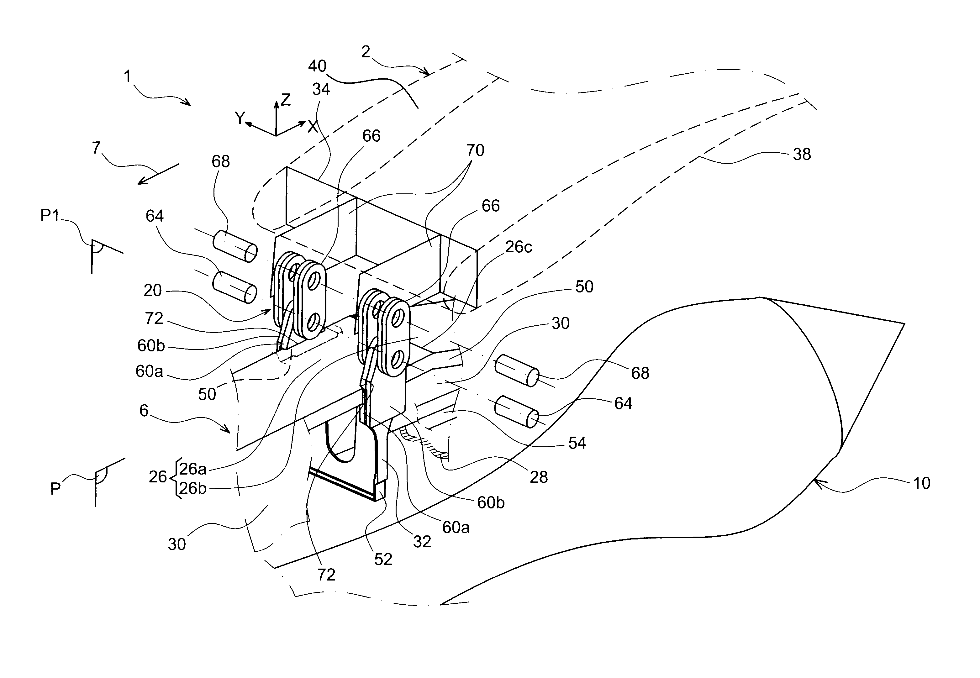
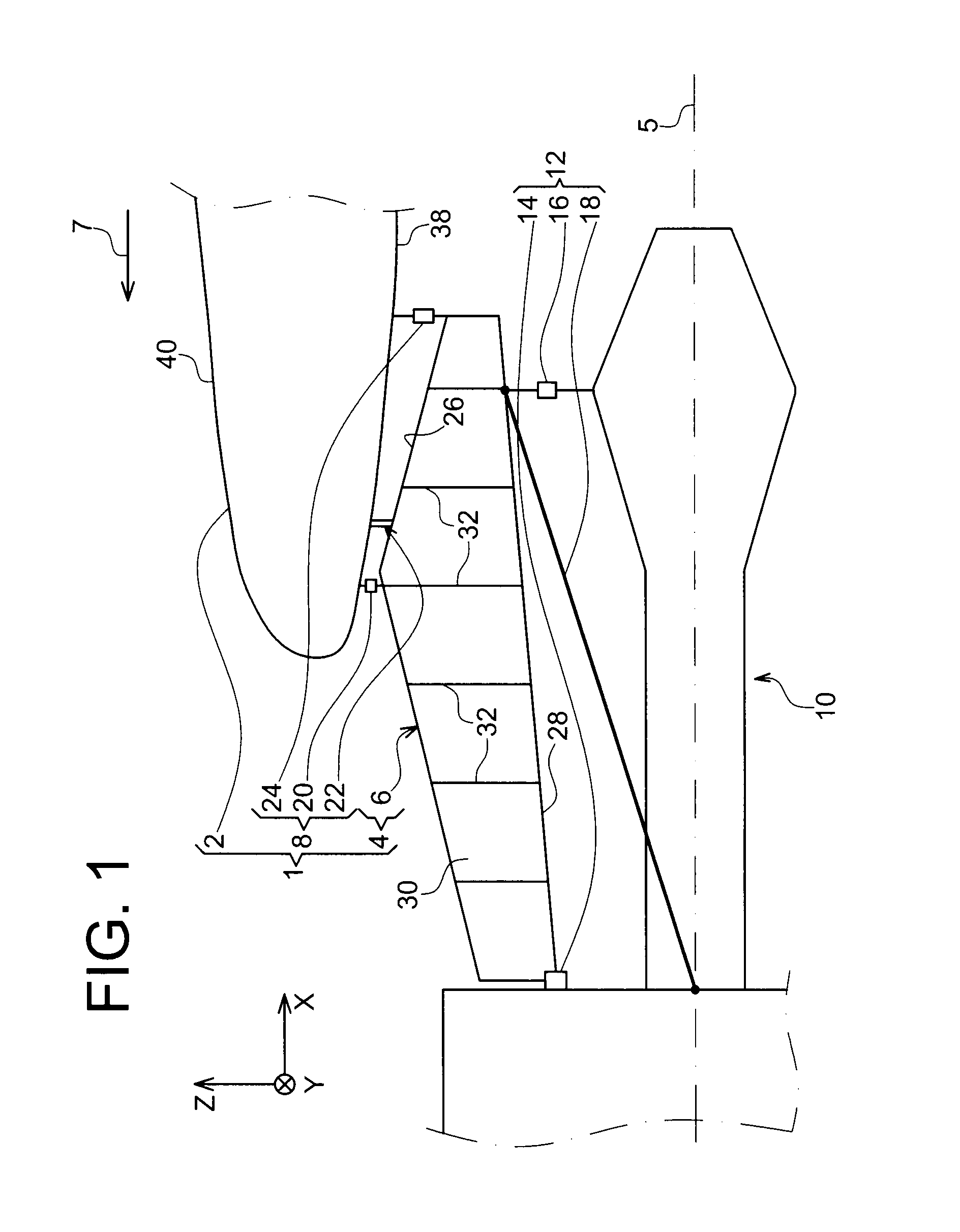
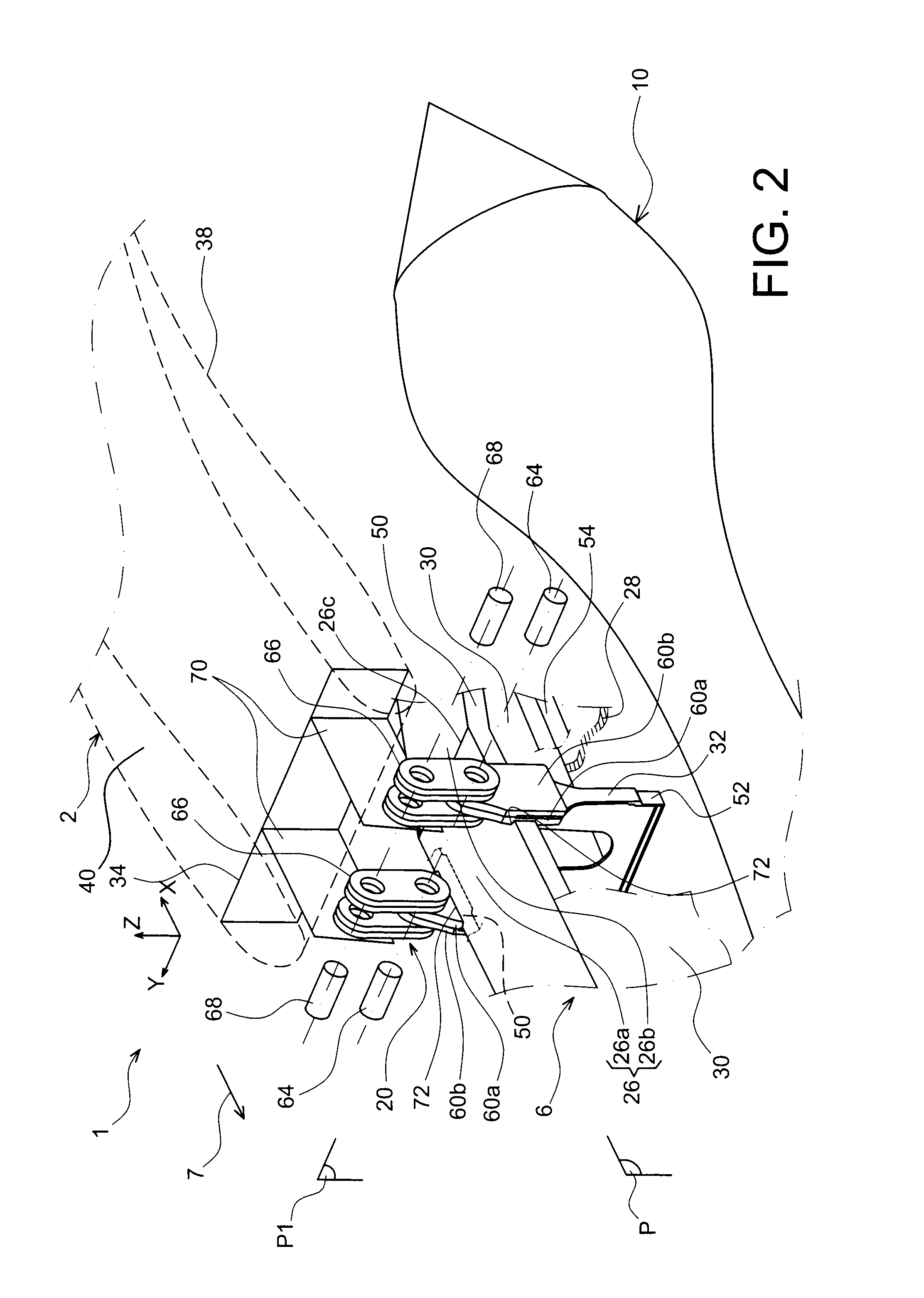
[0031]In reference to FIG. 1, this shows an aircraft assembly 1 according to a preferred embodiment of the present invention.

[0032]This assembly 1 overall comprises a wing element 2 such as a wing, an attachment pylon 4 of a turboengine such as a turbojet, and attachment means 8 of a rigid structure 6 forming a caisson of the pylon 4, under the wing element 2.

[0033]Also, by way of indication FIG. 1 illustrates attachment means 12 interposed between the rigid structure 6 and the turboengine 10, these means 12 being constituted by one or more front engine attachments 14, a rear engine attachment 16, and a thrust force collection device 18 essentially fitted with lateral takeup connecting rods.

[0034]These attachment means 12 are produced by conventional means, and accordingly require no further description.

[0035]Throughout the following description, conventionally, X is the longitudinal direction of the pylon 4 which is also equivalent to the longitudinal direction of the turbojet 10, ...


PUM


Abstract

An aircraft assembly including a wing element and an attachment pylon of a turboengine, including a rigid structure forming a caisson defined externally by a first longeron, a second longeron, and two lateral panels. The assembly also includes an attachment mechanism of the structure on the wing element, fitted with two front attachments, each including two first fittings solid with the associated lateral panel. For each front attachment, the two first fittings are arranged respectively on either side of their associated lateral panel.

Description

TECHNICAL FIELD[0001]The present invention relates in general to an aircraft assembly comprising a wing element forming a caisson and an attachment pylon of a turboengine on said wing element.[0002]The invention can be used on any type of aircraft equipped for example with turbojet engines or of turboprop engines.[0003]This type of attachment pylon, also known as “EMS” (for “Engine Mounting Structure”), for example suspends a turboengine below the wing of the aircraft, or else mounts this turboengine above this same wing.PRIOR ART[0004]Such an attachment pylon is in fact provided to constitute the linkage interface between an engine such as a turbojet engine and a wing of the aircraft. It transmits to the structure of this aircraft the forces generated by its associated turbojet engine, and also allows flow of fuel, electrical systems, hydraulics, and air between the engine and the aircraft.[0005]To ensure transmission of forces, the pylon comprises a rigid structure, often of the “...

Claims


Application Information

Patent Timeline
Patent Type & Authority Patents(United States)
IPC IPC(8): B64D27/00
CPCB64D27/26B64D2027/264B64D2027/266
Inventor GARDES, PASCALCOMBES, STEPHANE
Owner AIRBUS OPERATIONS (SAS)
Why Eureka
Try Eureka