
Rail system and method for assembly

a rail system and railing technology, applied in the field of railing components and systems, can solve the problems of difficult installation, significant on-site labor, and various drawbacks of known railing systems, and achieve the effects of enhancing the appearance of the railing, easy assembly on-site, and easy assembly

Active Publication Date: 2012-05-01
CPG INT
View PDF544 Cites 40 Cited by
  • Summary
  • Abstract
  • Description
  • Claims
  • Application Information

AI Technical Summary

Benefits of technology

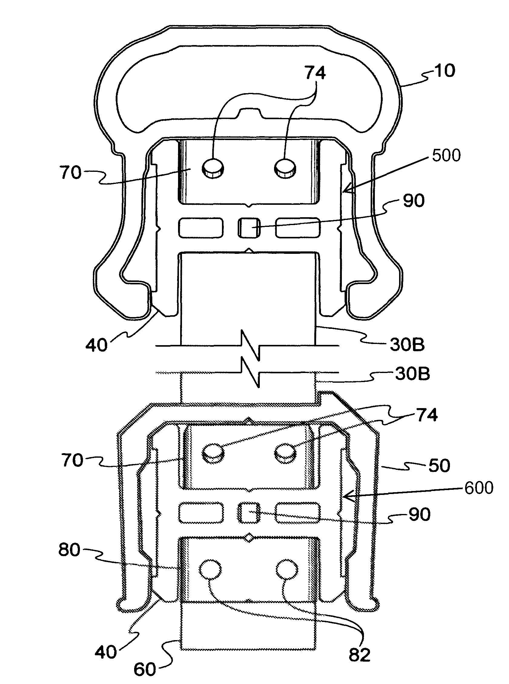
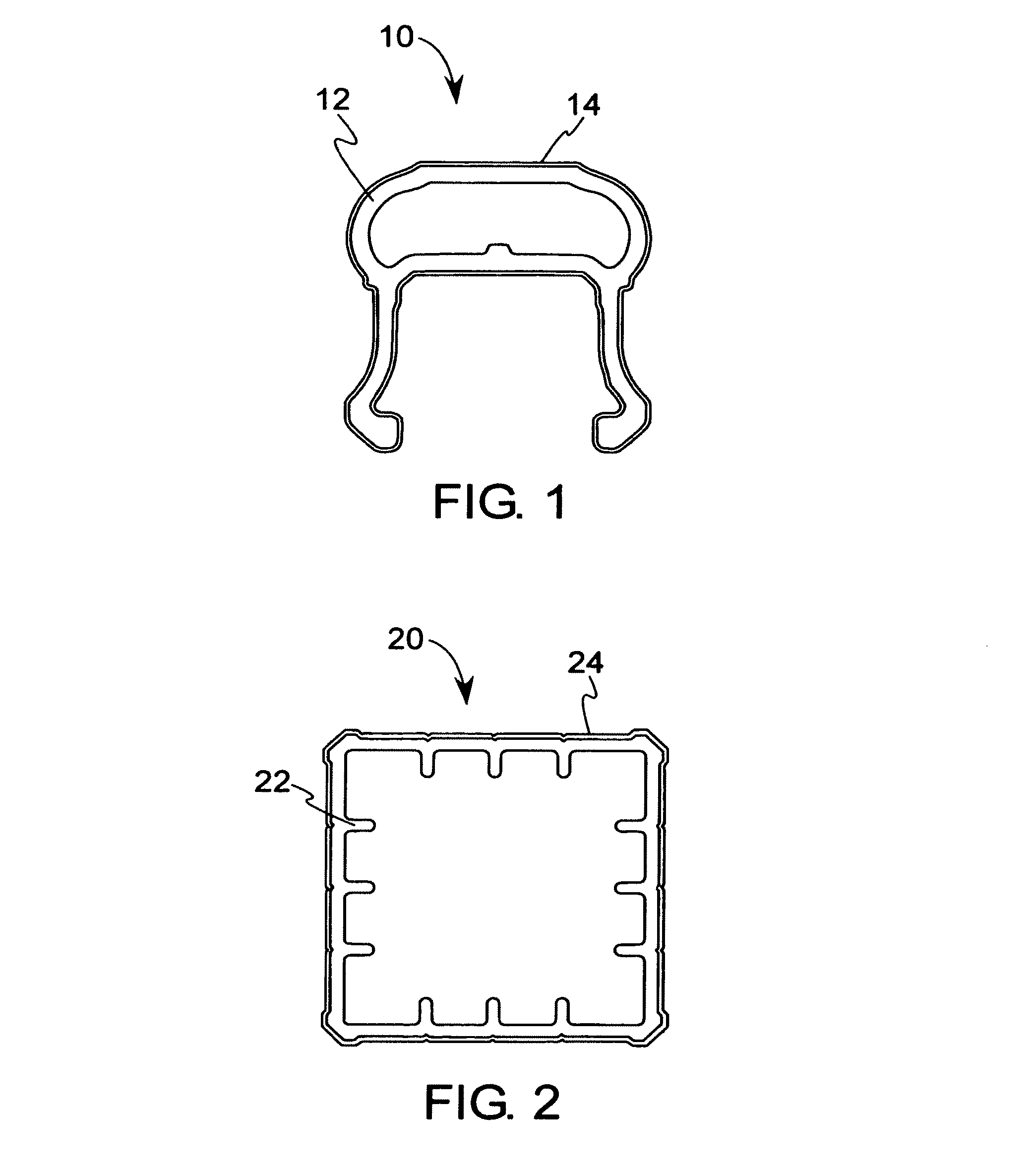
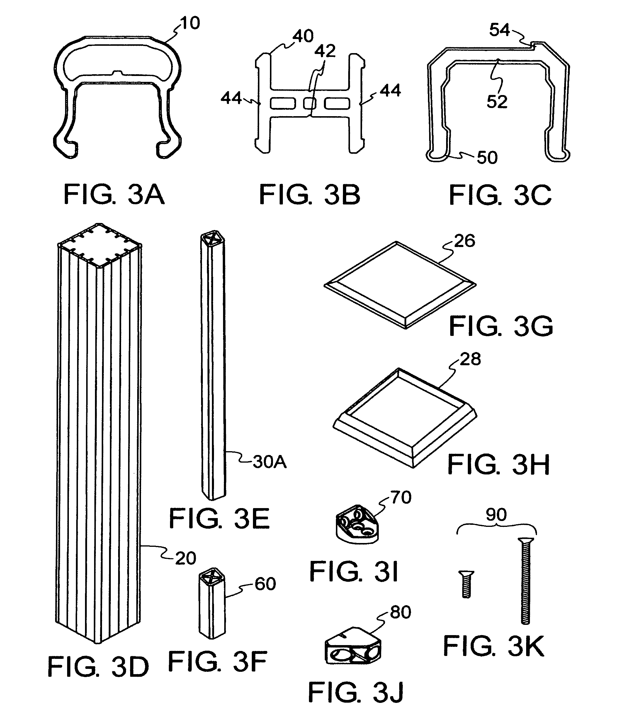
[0005]The present invention provides a rail system that may be comprised of any material that is suitable for the intended purpose of the railing. For example, the rail system may be comprised of a composite material that is durable and resistant to weathering. In addition, an exemplary embodiment of the rail system may be easily assembled on-site. If desired, the rail system may be at least partially pre-assembled at an off-site location. In one exemplary embodiment, the rail system may be uniquely designed to accommodate perpendicular and angled installations (e.g., both in the horizontal and vertical planes). In another exemplary embodiment, the rail system may be easily assembled such that the support hardware is substantially hidden from view after installation, thereby enhancing the appearance of the railing. In light of such benefits, the present invention may provide an easy to install, weather-resistant, safe, secure, and aesthetically pleasing rail system that is suitable for a variety of indoor and outdoor uses.

Problems solved by technology

Known railing systems suffer from various drawbacks.
For instance, many conventional railing systems are difficult to install, thereby requiring significant amounts of on-site labor.
In addition, many railing systems require an excessive number of parts in order to complete an installation.
As might be expected, the extra components may increase the complexity and cost of the manufacturing, shipping, and installation of the railing assembly.
On the other hand, some existing railing assemblies may not even allow angled installations.
Moreover, known railing systems may also fail to provide a desired aesthetic appearance.
For example, these railing systems may leave the support hardware exposed, which limits the visual appearance of the product.

Method used


Image

  • Rail system and method for assembly
  • Rail system and method for assembly
  • Rail system and method for assembly

Examples


examples

[0076]One example of a composite that may be used to make a component comprises ingredients in the following amounts:

[0077]

PARTS PER 100 PARTSINGREDIENTOF RESINWEIGHT PERCENTwood flour15055.1PVC resin10036.8lubricant7.52.8acrylic modifier62.2calcium carbonate51.8tin stabilizer2.50.9process aid10.4

[0078]Another example of a composite that may be used to make a component comprises ingredients in the following amounts:

[0079]

PARTS PER 100 PARTSINGREDIENTOF RESINWEIGHT PERCENTwood flour18360PVC resin10032.8lubricant7.52.5acrylic modifier62calcium carbonate51.6tin stabilizer2.50.8process aid10.3

[0080]A third example of a composite that may be used to make a component comprises ingredients in the following amounts:

[0081]

PARTS PER 100 PARTSINGREDIENTOF RESINWEIGHT PERCENTwood flour146.650.0PVC resin10034.1ABS resin18.46.3thermal stabilizer3.751.3lubricant103.4impact modifier6.02.1process aid10.3calcium carbonate7.52.6

[0082]A fourth example of a composite that may be used to make a component...


PUM


Abstract

A rail system that may be comprised of various components such as an upper rail, support rail, bottom rail, squash blocks, balusters, post covers, and ancillary components, such as post skirts and caps. In one exemplary embodiment, the rail system may be uniquely designed to accommodate perpendicular and angled installations (e.g., both in the horizontal and vertical planes). Furthermore, in another exemplary embodiment, the rail system may be easily assembled such that the support hardware is substantially hidden from view after installation, thereby enhancing the appearance of the railing.

Description

[0001]This application is a continuation of U.S. patent application Ser. No. 11 / 292,269, filed Nov. 30, 2005 now abandoned, which is hereby incorporated by reference in its entirety.TECHNICAL FIELD[0002]The present invention relates generally to railing components and systems and related methods for assembly.BACKGROUND AND SUMMARY OF THE INVENTION[0003]Railing systems have been used in various forms to protect and secure people, animals, and land. Railing systems have also been used to prevent entry into a designated area. While these functional railing uses continue today, railing systems may also be used for decorative purposes such as on porches and decks and around yards and gardens.[0004]Known railing systems suffer from various drawbacks. For instance, many conventional railing systems are difficult to install, thereby requiring significant amounts of on-site labor. In addition, many railing systems require an excessive number of parts in order to complete an installation. For...

Claims


Application Information

Patent Timeline
IPC IPC(8): E04H17/00
CPCE04F11/181E04H17/1488E04H17/1417E04H17/006E04H17/1473E04H17/1482E04F11/1834
Inventor BIZZARRI, PAUL M.HERR, CHIPPREVITE, JOHN M.BURT, KEVIN T.TAYLOR, WILLIAM G.FENNEMAN, MATTHEW T.BURR, JEFFREY R.ROTHWELL, TIMOTHY C.
Owner CPG INT
Learn More