Dielectric sealing member and method of use thereof

a sealing member and dielectric technology, applied in the direction of coupling device connection, coupling device base/case, two-part coupling device, etc., can solve the problems of poor electromagnetic shielding and intermittent contact, and achieve the effect of improving reliability

Inactive Publication Date: 2012-05-01
PPC BROADBAND INC
View PDF527 Cites 100 Cited by
  • Summary
  • Abstract
  • Description
  • Claims
  • Application Information

AI Technical Summary

Benefits of technology

[0007]The following disclosure provides an apparatus for use with coaxial cable connections that offers improved reliability.
[0009]A second general aspect of the invention provides a connector for coupling an end of a coaxial cable, the coaxial cable having a center conductor surrounded by a dielectric, the dielectric being surrounded by a foil layer, the foil layer being surrounded by a conductive grounding shield, the conductive grounding shield being surrounded by a protective outer jacket, the connector comprising a connector body attached to a post wherein the post has a first end and a second end, the first end configured to be inserted into an end of the coaxial cable around the foil layer encompassing the dielectric and under the conductive grounding shield thereof, a port coupling element attached to the post, and a sealing member positioned between the foil layer and the post, wherein the sealing member prevents environmental elements from entering the connector.
[0010]A third general aspect of the invention provides a connector for coupling an end of a coaxial cable, the coaxial cable having a center conductor surrounded by a dielectric, the dielectric being surrounded by a foil layer, the foil layer being surrounded by a conductive grounding shield, the conductive grounding shield being surrounded by a protective outer jacket, the connector comprising a connector body, having a first end and a second end, the first end configured to deformably compress against and seal a received coaxial cable, a post, attached to the connector body, a port coupling element, attached to the post, a sealing member located so as to prevent entry of external environmental elements between the post and the foil layer surrounding the dielectric, and a plurality of conductive members, the plurality of conductive members completing a shield preventing ingress of electromagnetic noise into the connector and facilitating grounding of the coaxial cable.
[0011]A fourth general aspect of the invention provides a connector for coupling an end of a coaxial cable, the coaxial cable having a center conductor surrounded by a dielectric, the dielectric being surrounded by a foil layer, the foil layer being surrounded by a conductive grounding shield, the conductive grounding shield being surrounded by a protective outer jacket, the connector comprising a connector body having a first end and a second end, the first end configured to deformably compress against and seal a received coaxial cable, wherein a post is attached to the connector body, a rotatable coupling element attached to the post, wherein the post has a first end and a second end, and means for sealing the dielectric against ingress of environmental elements without impeding advancing movement of the dielectric and the foil layer through post of the connector.

Problems solved by technology

In many instances, these coaxial cables are present outdoors, exposed to weather and / or otherwise exposed to numerous environmental elements.
Weathering and various environmental elements can work to create interference problems when metallic components corrode, deteriorate or become galvanically incompatible thereby resulting in intermittent contact and poor electromagnetic shielding.

Method used


Image

  • Dielectric sealing member and method of use thereof
  • Dielectric sealing member and method of use thereof
  • Dielectric sealing member and method of use thereof

Examples


Embodiment Construction

[0034]Although certain embodiments of the present invention will be shown and described in detail, it should be understood that various changes and modifications may be made without departing from the scope of the appended claims. The scope of the present invention will in no way be limited to the number of constituting components, the materials thereof, the shapes thereof, the relative arrangement thereof, etc., and are disclosed simply as an example of an embodiment. The features and advantages of the present invention are illustrated in detail in the accompanying drawings, wherein like reference numerals refer to like elements throughout the drawings.

[0035]As a preface to the detailed description, it should be noted that, as used in this specification and the appended claims, the singular forms “a”, “an” and “the” include plural referents, unless the context clearly dictates otherwise.

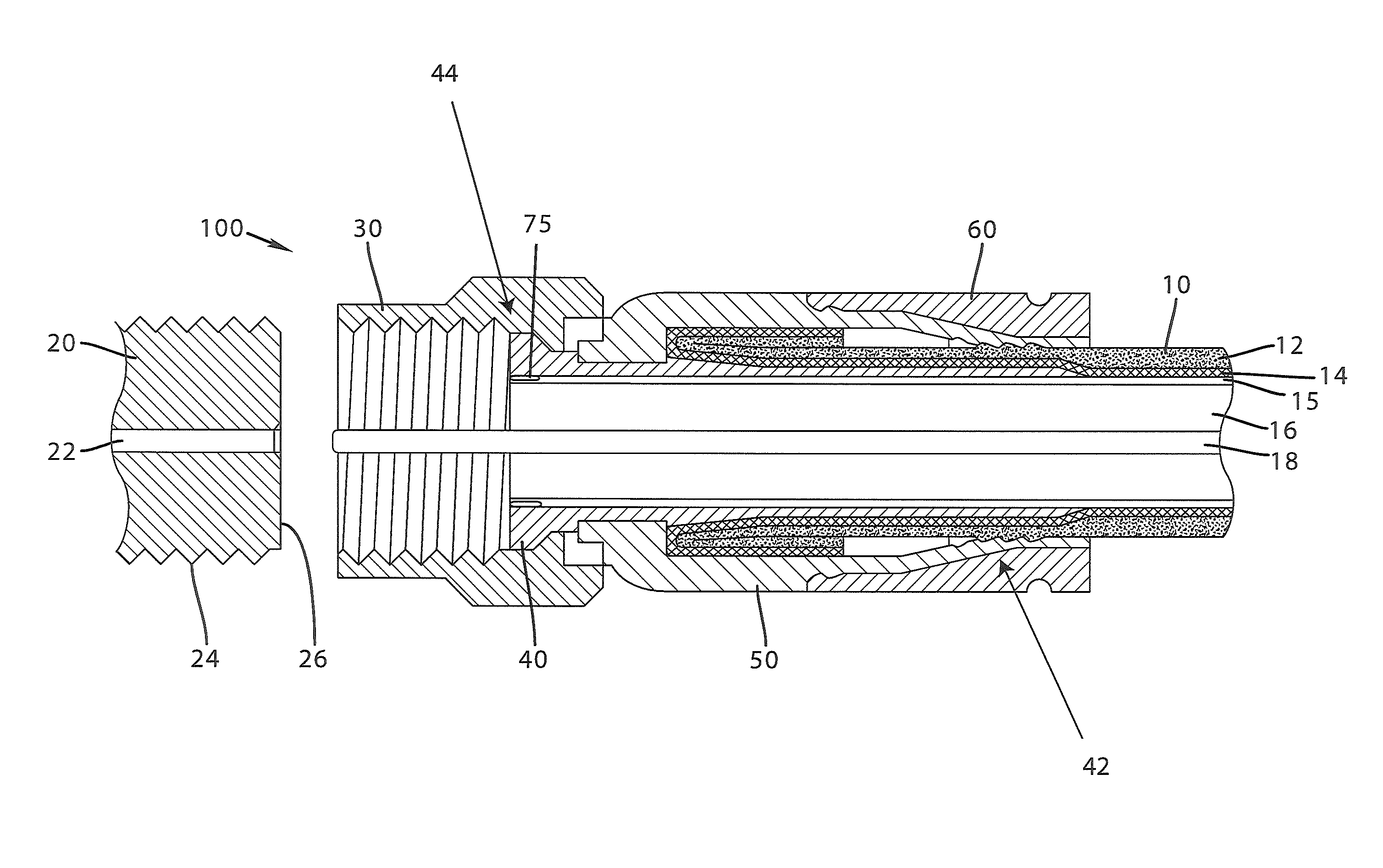
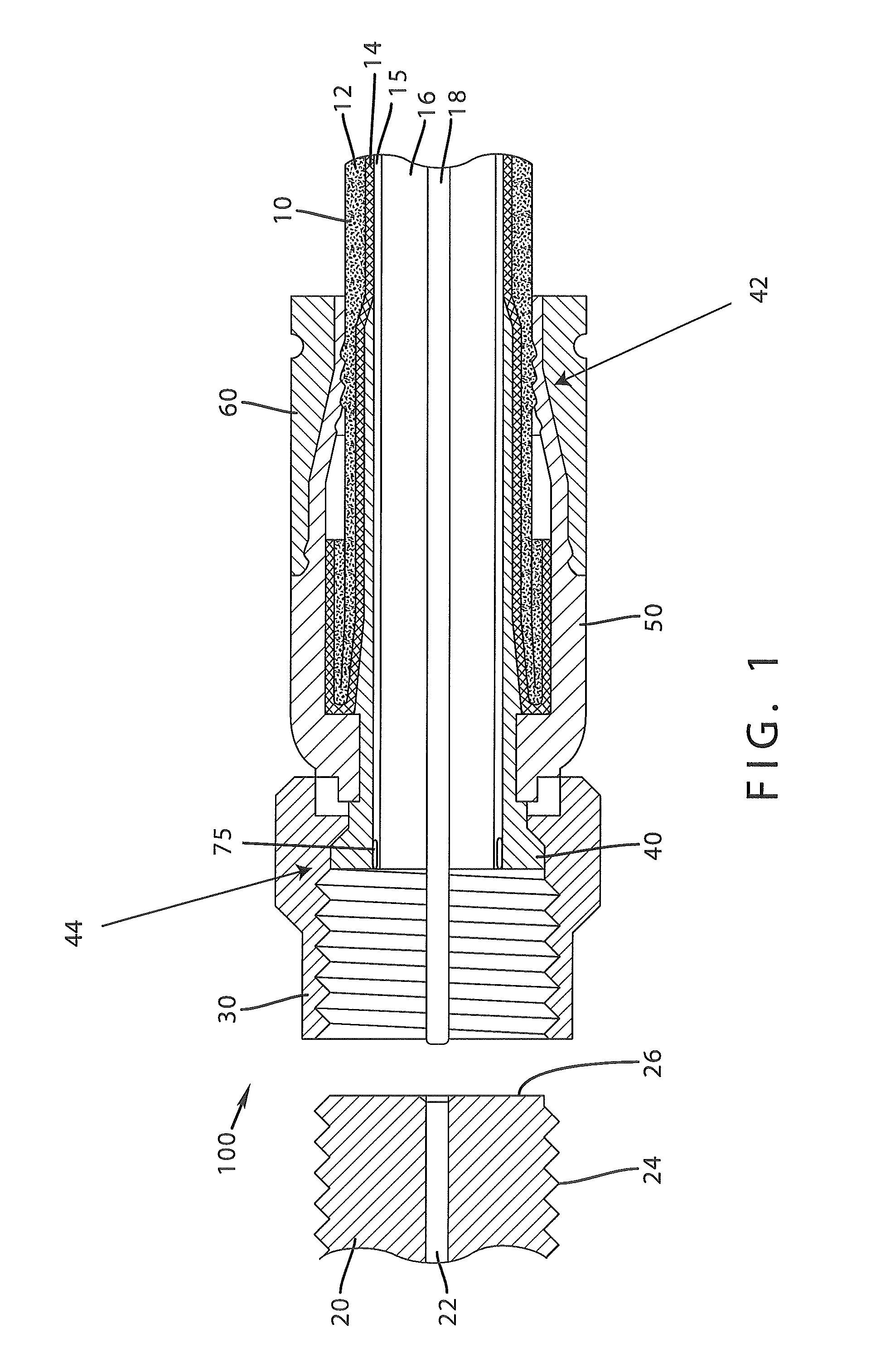
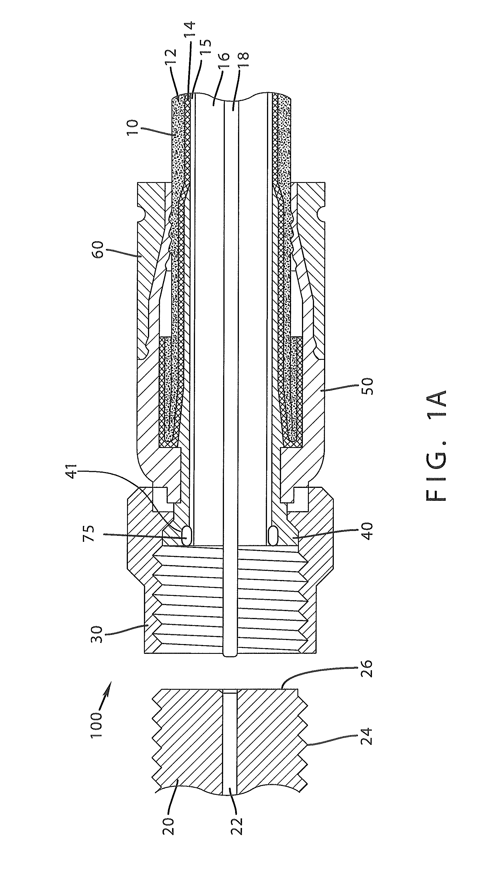
[0036]Referring to the drawings, FIG. 1 depicts one embodiment of a connector 100. The connector...


PUM


Abstract

A connector having a sealing member is provided, wherein the sealing member prevents environmental elements, such as rainwater from entering the connector. Furthermore, a sealing member placed on the inner surface of a post forming a barrier against moisture and other contaminants proximate the second end of the post is also provided.

Description

BACKGROUND[0001]1. Technical Field[0002]This invention relates generally to the field of connectors for coaxial cables. More particularly, this invention provides for a coaxial cable connector comprising at least one sealing member and a method of use thereof.[0003]2. Related Art[0004]Broadband communications have become an increasingly prevalent form of electromagnetic information exchange and coaxial cables are common conduits for transmission of broadband communications. Connectors for coaxial cables are typically connected onto complementary interface ports to electrically integrate coaxial cables to various electronic devices. In addition, connectors are often utilized to connect coaxial cables to various communications modifying equipment such as signal splitters, cable line extenders and cable network modules.[0005]In many instances, these coaxial cables are present outdoors, exposed to weather and / or otherwise exposed to numerous environmental elements. Weathering and variou...

Claims


Application Information

Patent Timeline
Patent Type & Authority Patents(United States)
IPC IPC(8): H01R13/52
CPCH01R13/5205H01R24/40H01R9/0524
Inventor MATHEWS, ROGER D.
Owner PPC BROADBAND INC
Why Eureka
Try Eureka