Reactor

a reactor and compact technology, applied in the direction of inductances, inductances with magnetic cores, continuous variable inductances/transformers, etc., can solve the problems of reducing the direct current resistance, increasing the current loss or the like, and the current resistance rdc of the winding becomes high, so as to reduce the size of the coil segment, the effect of lowering the distributed capacitance and high resonance frequency

Active Publication Date: 2012-05-01
DIAMOND&ZEBRA ELECTRIC MFG CO LTD
View PDF11 Cites 0 Cited by
  • Summary
  • Abstract
  • Description
  • Claims
  • Application Information

AI Technical Summary

Benefits of technology

[0011]Accordingly, the present invention has been devised to substantially eliminate the above discussed problems and inconveniences and is intended to provide a reactor having a good high frequency characteristic, which is simplified in structure and compact in size.
[0013]According to the above described construction, the coil segments of each of the auxiliary winding elements is of a multilayered and aligned winding structure and the respective coil segments of those first and second auxiliary winding elements are arranged respectively in the space areas each defined between the second and first auxiliary winding elements and the outside, with the coil segments of each of the first and second auxiliary winding elements positioned adjacently alternately in a line to form the main winding body and also to form the divided winding composed of a plurality of divided winding segments, with the first and second auxiliary winding elements being connected parallel to each other. For this reason, the main winding body is reduced in size; due to the divided winding, the overall distributed capacitance of the coil segments is lowered and, therefore, a high resonance frequency can be obtained; and due to the parallel connection, the overall serial resistance is lowered. Accordingly, with a simplified and compact construction, the reactor having a low direct current resistance and a good high frequency characteristic can be obtained.
[0014]In a preferred embodiment of the present invention, the coil segments of the first auxiliary winding element and the coil segments of the second auxiliary winding element are wound in respective directions reverse to each other and a winding start of the coil segments of the first auxiliary winding element and a winding end of the second auxiliary winding element are connected to form a parallel connection. Accordingly, the symmetry of arrangement of the coil segments at the input and output sides can be secured and since the impedance characteristic at the high frequency region remains the same at the input and output sides, the high frequency impedance can be stabilized.
[0015]A material for the winding wire may preferably be in the form of a round sectioned wire with a circular or elliptic sectional shape. Accordingly, since a all purpose wire is employed, a low cost can be accomplished. Also preferably, the main winding body is made up of two auxiliary winding elements and each of the first and second auxiliary winding elements is made up of two coil segments.
[0016]In another preferred embodiment of the present invention, the main coil body is provided in a pair and in which the core comprises a generally rectangular core made of the magnetic material and having a pair of arms that are inserted into respective hollows of the main winding bodies. Accordingly, the reactor having a good high frequency characteristic can be obtained with a simplified and compact construction.

Problems solved by technology

On the other hand, at the low frequency region, if the number of windings increase, the direct current resistance Rdc of the winding becomes high, accompanied by an increase of the current loss or the like.
On the other hand, lowering of the direct current resistance Rdc require the use of a wire thick enough to make it difficult to wind and also to compactize.
To reduce the length of the winding wire the use of the rectangular wire having a large vertical to lateral ratio (ratio between the height and the width) and, therefore, it is impossible to reduce the size of and the cost of the reactor.
On the other hand, the rectangular wire requires a high cost and requires an increased number of assembling steps, accompanied by a low yield.
Also, even where the volumetric efficiency comparable to that achieved by the edgewise winding is achieved by the use of the rectangular wire, simplification of the structure and reduction in cost cannot be accomplished sufficiently.

Method used


Image

  • Reactor
  • Reactor
  • Reactor

Examples


Embodiment Construction

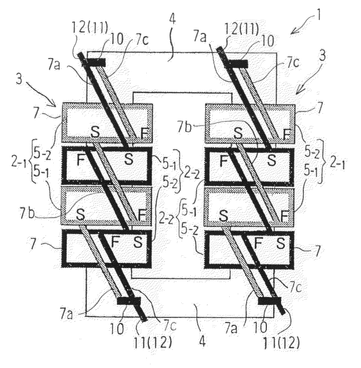
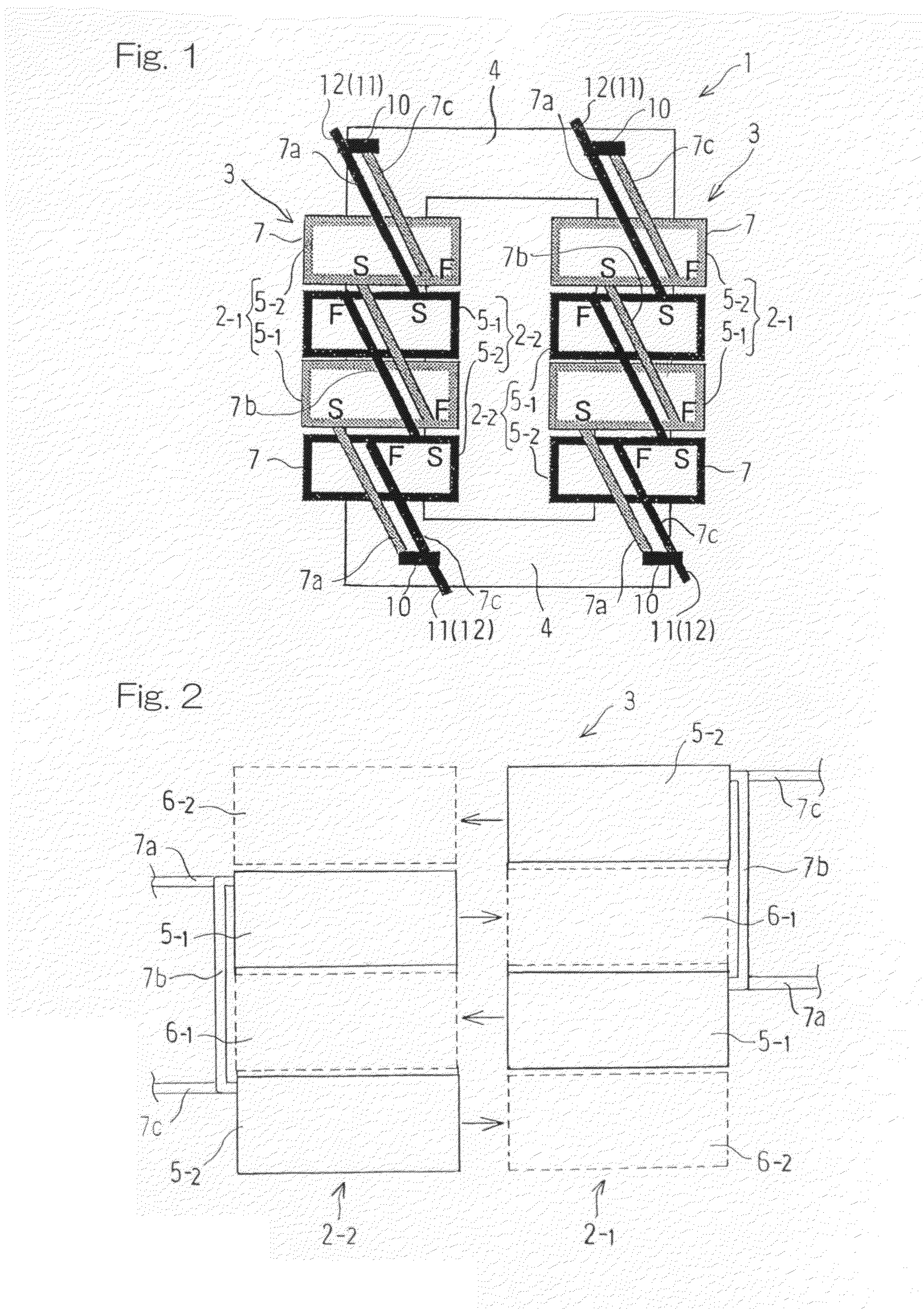
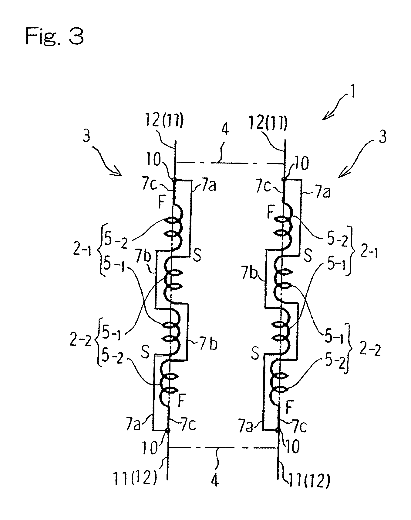
[0026]Hereinafter, a preferred embodiment of the present invention will be described in detail with reference to the accompanying drawings. In particular, FIG. 1 illustrates in a schematic top plan view, a reactor designed in accordance with the preferred embodiment of the present invention. The illustrated reactor 1 includes a pair of main winding bodies 3, each comprised of a plurality of, for example, two, pairs of first and second auxiliary winding elements 2-1 and 2-2, and is made up of a combination of those main winding bodies 3 and 3 with a generally rectangular core 4 made of a magnetic material and having bridges and arms assembled together to render it to represent a rectangular shape. While each of the main winding bodies 3 and 3 has a hollow bound by the corresponding winding, the main winding bodies 3 and 3 and the core 4 are assembled together with the core arms extending through the hollows.

[0027]In FIGS. 1 and 2, the symbol “S” represents the start of winding to for...


PUM

PropertyMeasurementUnit
magneticaaaaaaaaaa
frequencyaaaaaaaaaa
sizeaaaaaaaaaa

Abstract

A reactor is provided in which coil segments (5-1, 5-2) of each of first and second auxiliary winding elements (2-1, 2-2) is of a multilayered and aligned winding structure. The coil segments (5-1, 5-2) of the first auxiliary winding element (2-1) and the coil segments (5-1, 5-2) of the second auxiliary winding element (2-2) are disposed within respective space areas (6-1, 6-2) delimited between the coil segments of the second auxiliary winding element and an outside and between the outside and the coil segments of the first auxiliary winding element. The coil segments of each of those first and second auxiliary winding elements are so combined as to be adjacently alternately positioned in a line to thereby form a main winding body (3). The pair of the auxiliary winding elements are connected parallel to each other.

Description

BACKGROUND OF THE INVENTION[0001]1. Field of the Invention[0002]The present invention relates to a compact reactor having a simplified structure and also having a good high frequency characteristic.[0003]2. Description of the Prior Art[0004]The reactor has hitherto been desired to be of a design, in which it can be incorporated in various inverter or the like to remove, for example, switching noises, has a high performance, along with a compact size and a low cost, and a simplified structure and an easiness to manufacture. In the reactor as shown in FIG. 6A, the resonance frequency f0 at which resonance takes place at the inductance L and distributed capacitance C0 of the winding unit (coil) is expressed by the following equation and, when the frequency is lower than the resonance frequency f0, the winding unit acts as a reactor:f0=1 / (2π(L·C0)1 / 2)[0005]In general, in order to obtain the reactor which is compact in size and low in cost and has a high inductance L, in the case of a mu...

Claims


Application Information

Patent Timeline
Patent Type & Authority Patents(United States)
IPC IPC(8): H01F27/28H01F21/02H01F27/04
CPCH01F27/006H01F37/00H01F27/38
Inventor TABUCHI, TOSHIHIDEKUNIMI, TAKENORI
Owner DIAMOND&ZEBRA ELECTRIC MFG CO LTD
Why Eureka
Try Eureka