Optical module

a technology of optical modules and optical components, applied in the field of optical modules, can solve the problems of easy disconnection of differential transmission lines, and achieve the effect of good high-frequency characteristics

Active Publication Date: 2018-06-19
LUMENTUM JAPAN INC
View PDF14 Cites 0 Cited by
  • Summary
  • Abstract
  • Description
  • Claims
  • Application Information

AI Technical Summary

Benefits of technology

[0008]It is an object of the invention to provide an optical module with good high-frequency characteristics.
[0009](1) An optical module according to an aspect of the invention includes: an optical subassembly including a plurality of leads and being for converting an optical signal and an electric signal at least from one to the other; and a wiring board including a wiring pattern and overlapping and electrically connected to the optical subassembly, wherein the plurality of leads include a pair of differential signal leads for receiving differential signals, and a power supply lead for supplying power, the wiring pattern includes a pair of differential transmission lines connected to the pair of differential signal leads, and a power supply wiring connected to the power supply lead, the wiring board includes a first region overlapping the optical subassembly, and a second region extending from the first region so as to protrude from the optical subassembly, the pair of differential signal leads are farther away from the second region than the power supply lead, the pair of differential transmission lines are close together so as to be electromagnetically coupled to each other, and the optical subassembly does not include a lead penetrating the wiring board in a region between the pair of differential transmission lines. According to the aspect of the invention, since the pair of differential signal leads are farther away from the second region (region protruding from the optical subassembly) than the power supply lead, the power supply lead serves as a bend stop of the wiring board. The pair of differential transmission lines are prone to disconnection when bent at bonding portions to the pair of differential signal leads. However, the power supply lead serves as a bend stop of the wiring board, so that disconnection is prevented. Moreover, the pair of differential transmission lines are not away from each other because of the absence of the lead in the region therebetween. Therefore, there is no impedance mismatch, and thus high-frequency characteristics are good.

Problems solved by technology

The pair of differential transmission lines are prone to disconnection when bent at bonding portions to the pair of differential signal leads.

Method used


Image

  • Optical module
  • Optical module
  • Optical module

Examples


Embodiment Construction

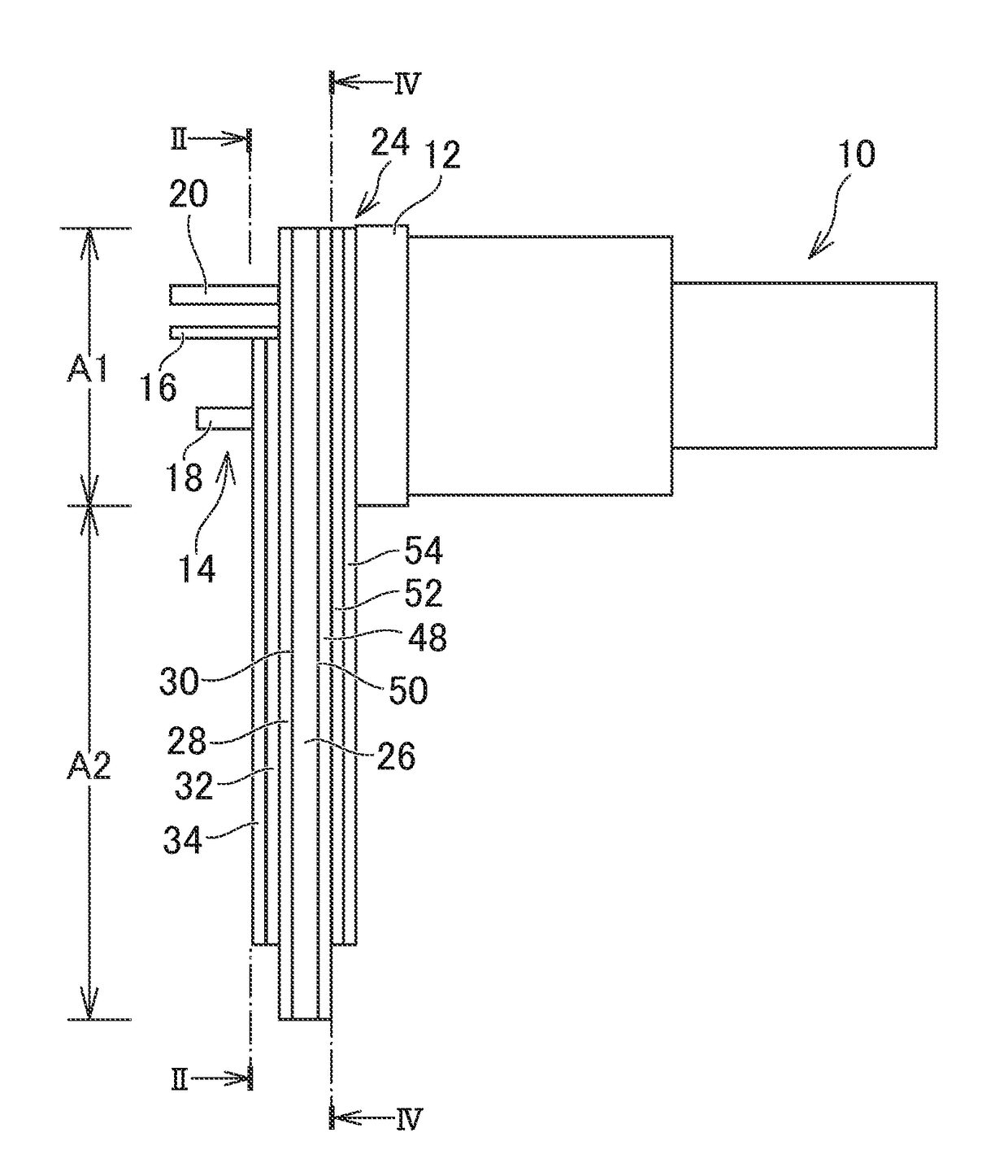
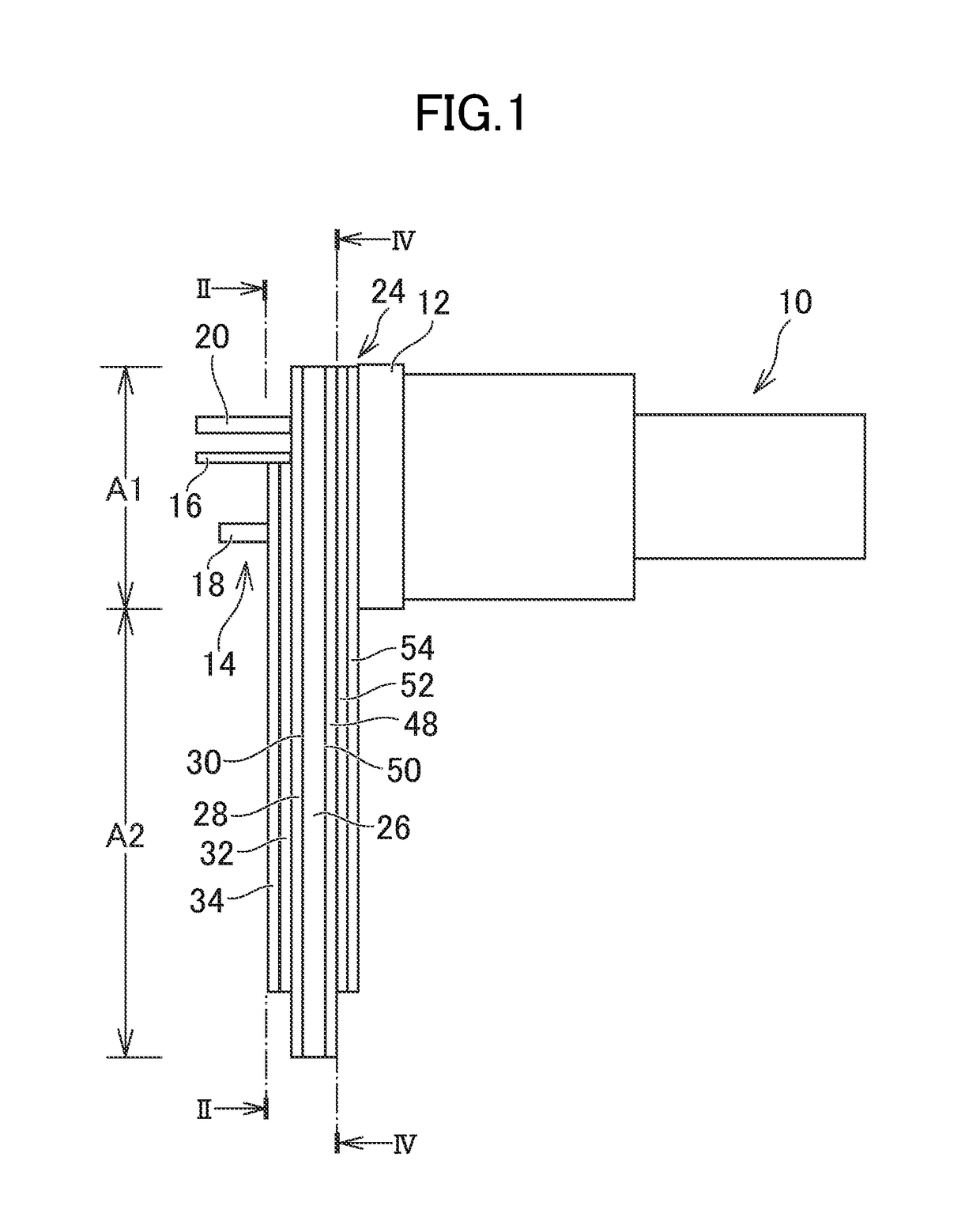
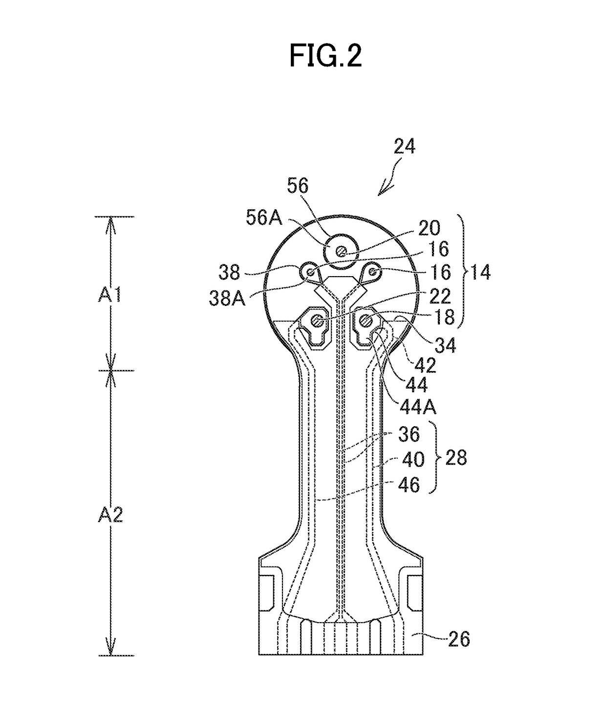
[0022]Hereinafter, an embodiment of the invention will be described with reference to the drawings. FIG. 1 is a cross-sectional view showing an overview of an optical module according to the embodiment of the invention. FIG. 2 is a cross-sectional view of the optical module shown in FIG. 1, taken along line II-II.

[0023]The optical module includes an optical subassembly 10. One example of the optical subassembly 10 is an optical transmitter module (transmitter optical subassembly (TOSA)) that includes a light-emitting element such as a laser therein, converts an electric signal to an optical signal, and transmits the optical signal to an optical fiber connected with an optical connector. Another example is an optical receiver module (receiver optical subassembly (ROSA)) that includes a light-receiving element typified by a photodiode therein and converts the optical signal received through the optical connector to the electric signal. Alternatively, a bidirectional optical subassembl...


PUM


Abstract

A plurality of leads include a pair of differential signal leads for inputting differential signals, and a power supply lead for supplying power. A wiring pattern includes a pair of differential transmission lines connected to the pair of differential signal leads, and a power supply wiring connected to the power supply lead. A wiring board includes a first region overlapping an optical subassembly, and a second region extending from the first region so as to protrude from the optical subassembly. The pair of differential signal leads are farther away from the second region than the power supply lead. The pair of differential transmission lines are close together so as to be electromagnetically coupled to each other. The optical subassembly does not include a lead penetrating the wiring board in a region between the pair of differential transmission lines.

Description

CROSS-REFERENCE TO RELATED APPLICATION[0001]The present application claims priority from Japanese application JP2015-242275 filed on Dec. 11, 2015, the content of which is hereby incorporated by reference into this application.BACKGROUND OF THE INVENTION[0002]1. Field of the Invention[0003]The present invention relates to an optical module.[0004]2. Description of the Related Art[0005]A CAN-type optical module (also referred to as “optical subassembly” (OSA)) used in optical communications includes a CAN-type optical package in which an optical semiconductor device that performs photoelectric conversion is mounted, and a flexible board for electrically connecting the CAN-type optical package with a main board (JP 2009-302438 A and JP 2007-287767 A). On the flexible board, a pair of differential transmission lines are provided close together so that the pair of differential transmission lines are electromagnetically coupled together to obtain desired characteristic impedance.[0006]The...

Claims


Application Information

Patent Timeline
Patent Type & Authority Patents(United States)
IPC IPC(8): G02B6/42H01L31/02H05K1/02H05K1/11H05K1/18H05K3/34
CPCG02B6/4279G02B6/428G02B6/4245G02B6/4246G02B6/4263H05K1/0245H05K1/111H05K1/181G02B6/4238H05K1/118H05K3/3447H05K2201/10121H01L31/02013H01L31/04Y02E10/50
Inventor KOMATSU, KAZUHIRONOGUCHI, DAISUKE
Owner LUMENTUM JAPAN INC
Why Eureka
Try Eureka