
Tactile device with force sensitive touch input surface

a technology of touch input surface and tactile input, which is applied in the direction of coding, pulse technique, instruments, etc., can solve the problems of increasing the price and size of the input device, and achieve the effect of simplifying data communication and reducing device costs

Active Publication Date: 2012-05-01
WISETOUCH CO LTD
View PDF55 Cites 66 Cited by
  • Summary
  • Abstract
  • Description
  • Claims
  • Application Information

AI Technical Summary

Benefits of technology

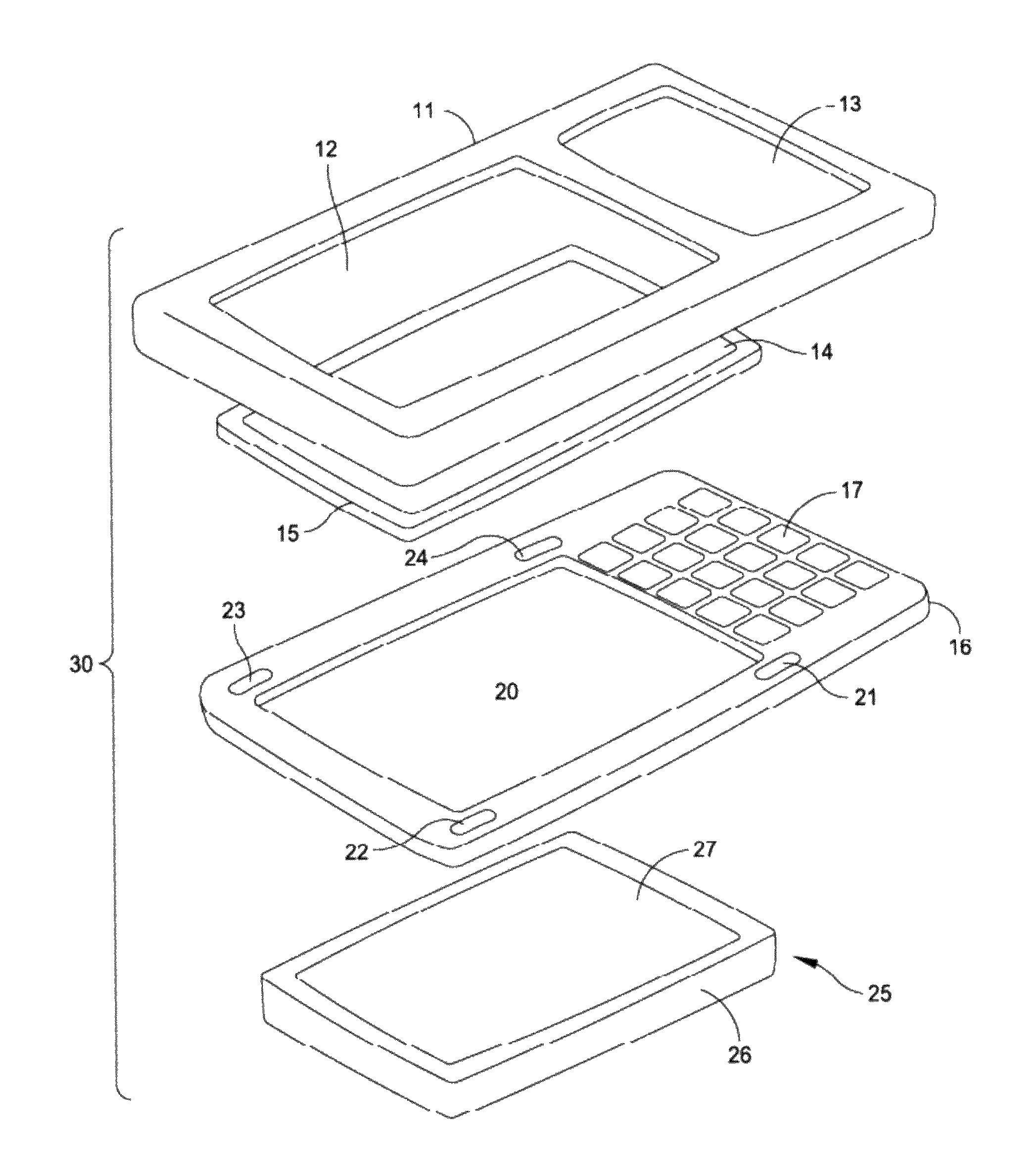
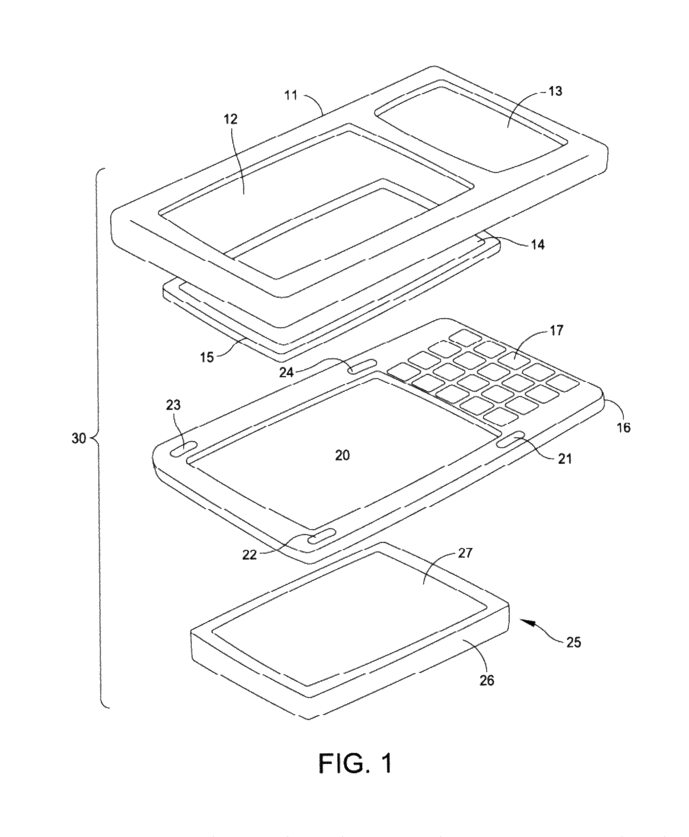
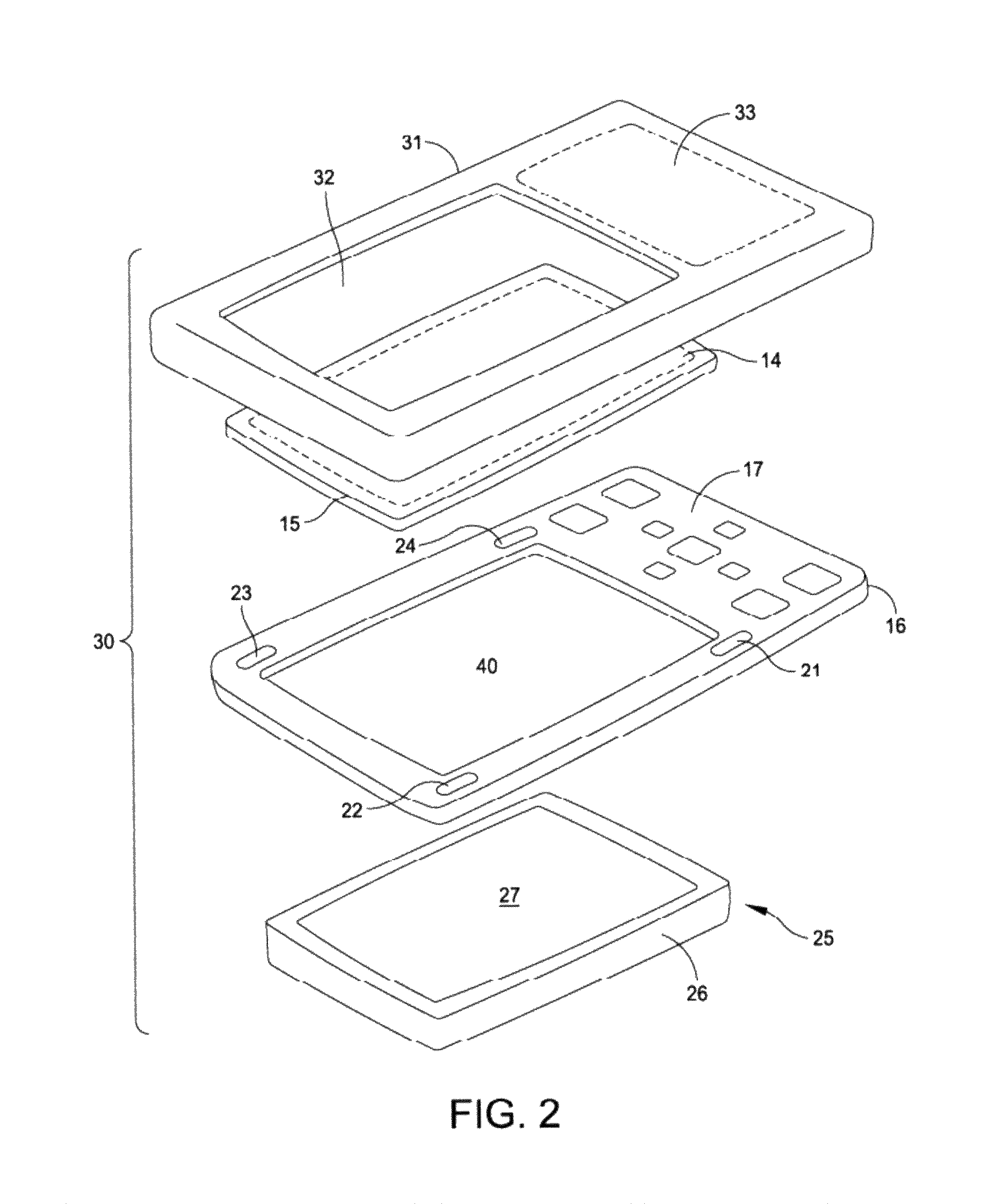
"This patent describes a tactile input device with an integrated touch screen display or other touch input surface. The device is designed to minimize costs and simplify data communication with external devices. It also allows for a universal touch surface input that can handle a touch screen as well as a multi-touch input keypad and specialty buttons such as a pressure sensitive scroll side button. The device includes a force-sensitive touch-responsive input device with a display and a planar electronics assembly that supports the display. The device includes a capacitive sensing device with a discrete first electrode and a peripheral conductive frame that acts as a second electrode. A complaint structure is proximate each discrete first electrode to determine the orientation of the display with respect to the planar electronics assembly during a touch. The processor that controls the image on the display monitors the capacitance of each capacitive sensing device to determine the force and location of a touch on the display."

Problems solved by technology

This may further increase the price and size of the input device to accommodate the different circuits in the device or require more complex signal transfers to external electronic and processing components.

Method used


Image

  • Tactile device with force sensitive touch input surface
  • Tactile device with force sensitive touch input surface
  • Tactile device with force sensitive touch input surface

Examples


second embodiment

[0066]FIG. 9 depicts one portion of a device that can provide the functions described above with reference to FIG. 7. This embodiment 170 includes an enclosure base 171 with a plurality of standoffs, such as standoff 172, for supporting a PC board 141. The PC board 141 defines a reference surface 173. Another spacer 174 positions an extension of an electric shield 175 beyond the periphery of the glass cover 142 to which it attaches. A fastener, such as a screw 176, completes the support structure. An L-shaped peripheral enclosure cover 177 overlies and protects this structure.

[0067]FIG. 9 also depicts one sensor location 144n. At this location a first electrode is formed by the electric shield 175 as a solid and continuous ground plate. It is spaced above a second electrode 178 formed on the reference surface 173. In this embodiment the first electrode acts as a ground electrode and moves with the glass cover 142 while the second electrode 178 remains stationary. The electrodes 178 ...

third embodiment

[0069]FIG. 10 depicts one portion of a device that can provide the functions described above with reference to FIG. 7. This embodiment 180 includes an enclosure base 181 for supporting the PC board 141 and the glass cover 142 which includes an electric shield 185 and an L-shaped peripheral enclosure cover 187. In this embodiment, standoffs and screws, such as shown at 182, depend from the cover 187 to support the electric shield 185 with the glass cover 142 and provide the necessary flexure. Other standoffs, such as a spacer 184, also depend from the cover 187 to position the PC board 141 with the reference surface 183.

[0070]In this embodiment the structure of the sensor at sensor location 144n includes a first electrode 189 that is formed on the electric shield 185. This construction enables better control of electrode spacing by using a structural frame 187. In this configuration, the electric shield 185 and the electrodes 189 form discrete ground electrodes spaced above second el...


PUM


Abstract

A tactile device includes a touch input surface in any number of forms including a force sensitive touch screen. In this embodiment a cover captures a transparent screen located on capacitive sensors. Touching the screen produces signals from each sensor that can be combined to identify the location of the touch and the force exerted by that touch.

Description

CROSS REFERENCE TO RELATED APPLICATION[0001]This application claims priority from U.S. Provisional Patent Application Ser. No. 61 / 040,672 filed Mar. 30, 2008.BACKGROUND OF THE INVENTION[0002]1. Field of the Invention[0003]This invention generally relates to tactile input devices and more specifically to tactile input devices with integral touch input surfaces.[0004]2. Description of Related Art[0005]Tactile input devices are becoming more popular in a variety of applications. Cellular telephones, personal digital assistants (PDAS) and other electronic devices seek to incorporate greater numbers of functions in such devices for a given volume. Tactile input devices can provide this capability. This has led to a number of approaches for providing input devices that utilize capacitive, resistive, strain gauge and other types of sensors.[0006]For example, U.S. Pat. Pub. No. 2007 / 0257821 to Son et al. (assigned to the same assignee as the present invention) and granted on Oct. 27, 2009 a...

Claims


Application Information

Patent Timeline
Patent Type & Authority Patents(United States)
IPC IPC(8): G08B21/00
CPCG06F3/0414G06F3/0418G06F3/04142G06F3/04186
Inventor SON, JAE
Owner WISETOUCH CO LTD
Learn More