
Flexible reduced bandwidth compressed video decoder

a compressed video and reduced bandwidth technology, applied in the field of digital video decoding, can solve the problems of lossy methods, decoding compressed video is typically expensive, and the lossy methods introduce drift (errors) in the decoded video, so as to reduce the amount of memory bandwidth reduction, and reduce the bandwidth

Active Publication Date: 2012-05-01
AVAGO TECH INT SALES PTE LTD
View PDF9 Cites 20 Cited by
  • Summary
  • Abstract
  • Description
  • Claims
  • Application Information

AI Technical Summary

Benefits of technology

The present invention provides a method for decoding video using a flexible reduced bandwidth compressed video decode. This method reduces memory bandwidth consumption, leaves reference data unmodified, and dynamically alter the amount of memory bandwidth reduction. Additionally, this method uses fewer taps in decoding interpolation and provides a low-cost implementation of a decoder.

Problems solved by technology

Decoding compressed video is typically expensive in terms of a dynamic random access memory (DRAM) bandwidth.
Existing lossless methods introduce significant cost by implementing large on-chip caches.
Existing lossy methods introduce drift (errors) in the decoded video, as the current lossy methods involve modifying the reference data.
For newer codecs (i.e., H.264 / MPEG4-AVC) the errors introduced by existing lossy methods are significantly exasperated by recursive in-loop deblocking filtering and recursive intra in-picture prediction from reconstructed pixels.
As such, existing lossy methods are visually unacceptable for some newer codecs.
Conventional methods using subsampling and reference frame compression can result in memory storage reduction, but often fail to give any significant worst-case memory bandwidth savings in practice, depending on the specific method, memory architecture and codec.

Method used


Image

  • Flexible reduced bandwidth compressed video decoder
  • Flexible reduced bandwidth compressed video decoder
  • Flexible reduced bandwidth compressed video decoder

Examples


Embodiment Construction

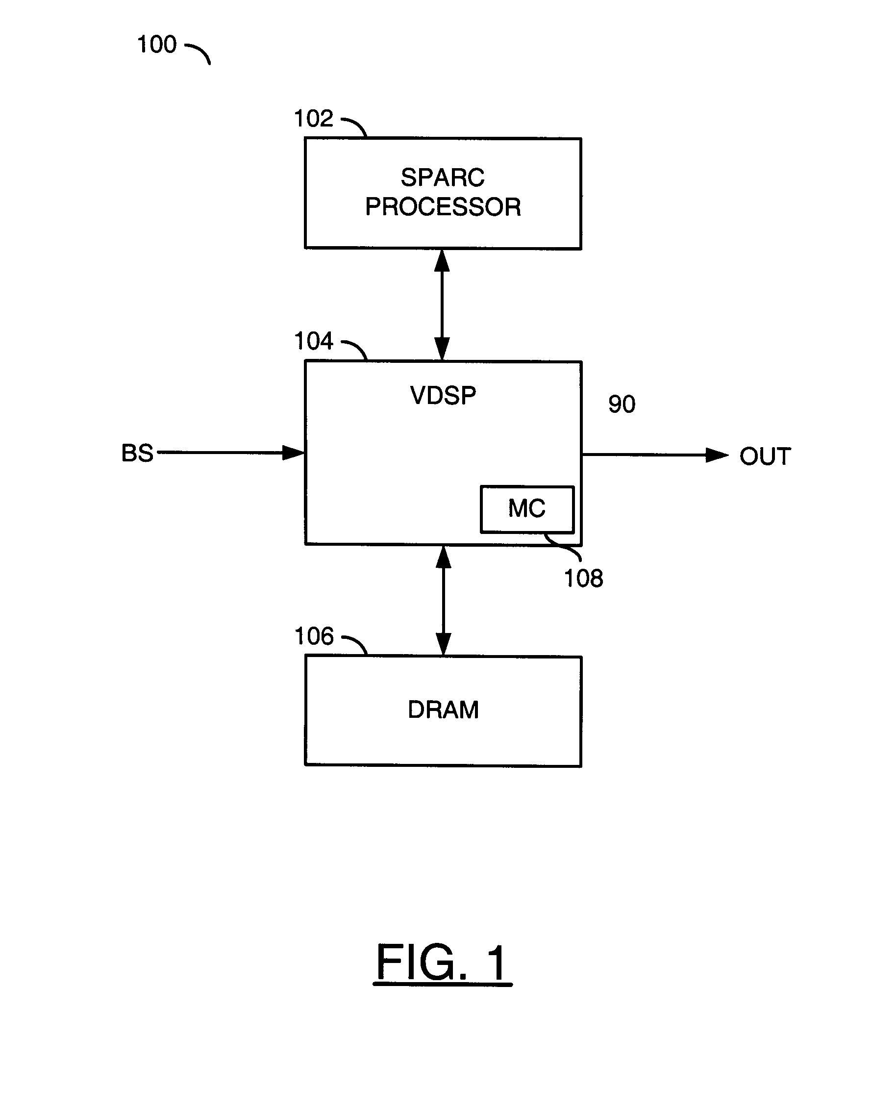
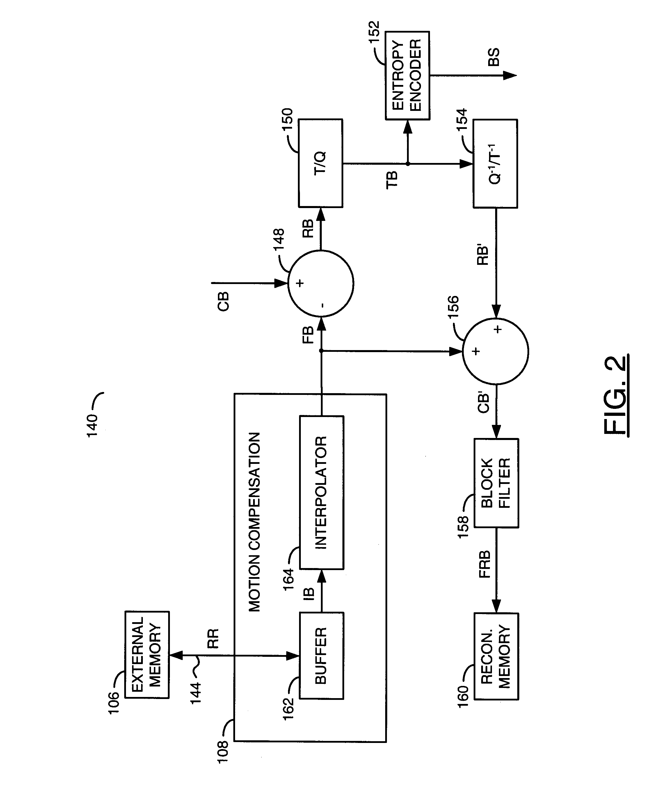
[0012]Referring to FIG. 1, a block diagram of an example implementation of a system 100 in accordance with a preferred embodiment of the present invention is shown. The system (or apparatus) 100 may implement a video decoder. The system 100 generally comprises a circuit (or module) 102, a circuit (or module) 104 and a circuit (or module) 106. The circuit 104 may be directly coupled to the circuit 102 and the circuit 106. A signal (e.g., BS) may be received by the circuit 104. A signal (e.g., OUT) may be presented by the circuit 104.

[0013]The signal BS may be a compressed video signal, generally referred to as a bitstream. The signal BS may comprise a sequence of progressive-format frames and / or interlace-format fields. The signal BS may be compliant with a VC-1, MPEG and / or H.26x standard. The MPEG / H.26x standards generally include H.261, H.264, H.263, MPEG-1, MPEG-2, MPEG-4 and H.264 / AVC. The MPEG standards may be defined by the Moving Pictures Expert Group, International Organizat...


PUM


Abstract

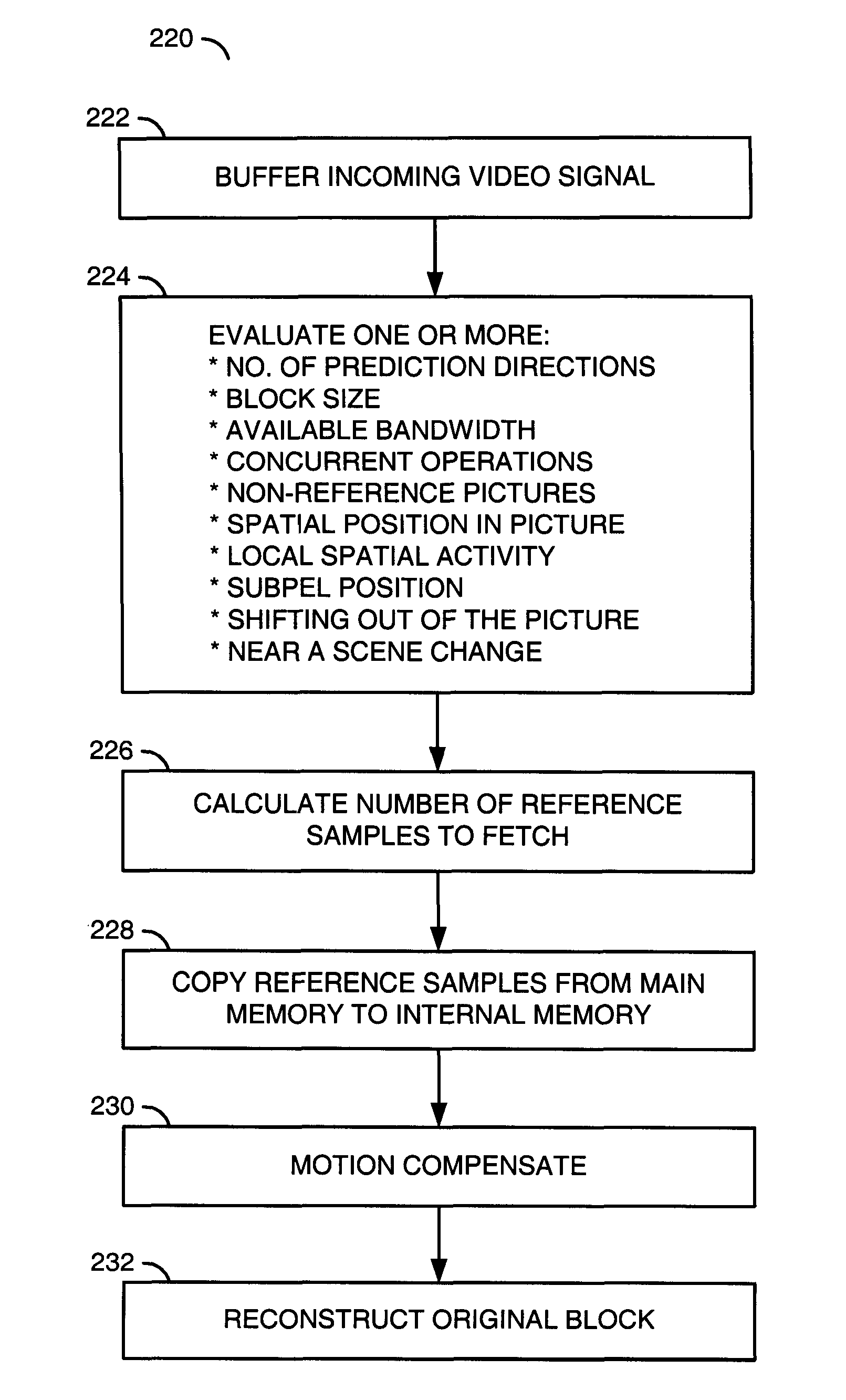
A method of decoding a video bitstream is disclosed. The method generally includes the steps of (A) buffering the video bitstream in a main memory, the video bitstream comprising a first residual block based on a first motion compensated block, the first motion compensated block having been generated by a subpixel motion compensation using an N-tap interpolation on a plurality of first reference samples, (B) copying a first subset of the first reference samples from the main memory to an internal memory, (C) generating a first decode block using the subpixel motion compensation with an M-tap interpolation on the first subset in the internal memory, and (D) reconstructing a first original block by adding the first residual block to the first decode block.

Description

FIELD OF THE INVENTION[0001]The present invention relates to digital video decoding generally and, more particularly, to a method and / or apparatus for implementing a flexible reduced bandwidth compressed video decode.BACKGROUND OF THE INVENTION[0002]Decoding compressed video is typically expensive in terms of a dynamic random access memory (DRAM) bandwidth. Newer codecs use more bandwidth than established codecs due to smaller block sizes (i.e., down to 4×4 blocks instead of 16×16 blocks), larger video formats (i.e., high definition) and more accurate subpixel interpolations (i.e., 6-tap interpolations instead of 2-tap interpolations). Existing approaches to deal with the DRAM bandwidth problem in decoders include lossy methods (i.e., compressing or subsampling reference data and dropping fields or frames) and lossless methods (i.e., storing reference frames or portions thereof in on-chip caches).[0003]Existing lossless methods introduce significant cost by implementing large on-chi...

Claims


Application Information

Patent Timeline
Patent Type & Authority Patents(United States)
IPC IPC(8): H04N11/02
CPCH04N19/61H04N19/117H04N19/523H04N19/82H04N19/433H04N19/44
Inventor WINGER, LOWELL L.
Owner AVAGO TECH INT SALES PTE LTD
Learn More