Method for the digital compensation of nonlinearities in a communication system and receiver device

a communication system and nonlinearity technology, applied in the field of digital compensation of nonlinearities in the communication system and the receiver device, can solve the problems of disturbing the reconstitution of information carried, and achieve the effects of saving energy, reducing the number of devices, and increasing the mobile use tim

Active Publication Date: 2012-05-01
COMMISSARIAT A LENERGIE ATOMIQUE ET AUX ENERGIES ALTERNATIVES
View PDF9 Cites 15 Cited by
  • Summary
  • Abstract
  • Description
  • Claims
  • Application Information

AI Technical Summary

Benefits of technology

[0013]In this way, it is possible to compensate for the nonlinearities present at the transmitter end, in other words generated or induced by the transmitter, for example generated by a power amplifier present in the transmitter, and / or at the receiver end, generated or induced by the receiver, for example by a Low Noise Amplifier (LNA), by a frequency mixer or a Variable Gain Amplifier (VGA) of a communication system.
[0015]The complexity of the algorithms for compensating for the nonlinearities is transferred to reception, which is particularly advantageous, especially where cellular networks are concerned. For example, in the case of an uplink between a mobile terminal and a base station, it is preferable to transfer the constraints to the base station, which has greater signal processing capacity compared with the mobile terminal. Since power amplification represents a large part of the power consumed by the mobile terminal the efficiency gain obtained at this level through the use of nonlinear components, like the amplifier, allows the mobile use time to be significantly increased or the energy saved to be transferred to other on-board applications.
[0016]It is therefore possible to get free of transmitter and / or receiver response nonlinearities which are a nonlinear function of the power (amplitude) of the transmitter and / or receiver input signal, unlike the channel nonlinearities, corresponding to the propagation channel frequency response, which are not linked to the amplitude of the transmitted signal.

Problems solved by technology

Under the effects of the nonlinearities of these elements, a variable power signal transmitted in one of these communication systems is distorted, disturbing the reconstitution of the information carried by this signal at reception.

Method used


Image

  • Method for the digital compensation of nonlinearities in a communication system and receiver device
  • Method for the digital compensation of nonlinearities in a communication system and receiver device
  • Method for the digital compensation of nonlinearities in a communication system and receiver device

Examples


Embodiment Construction

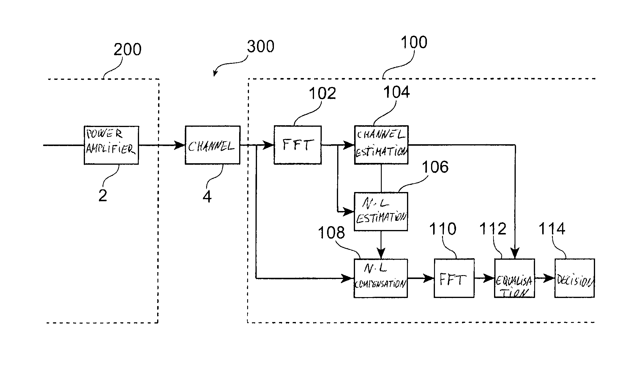
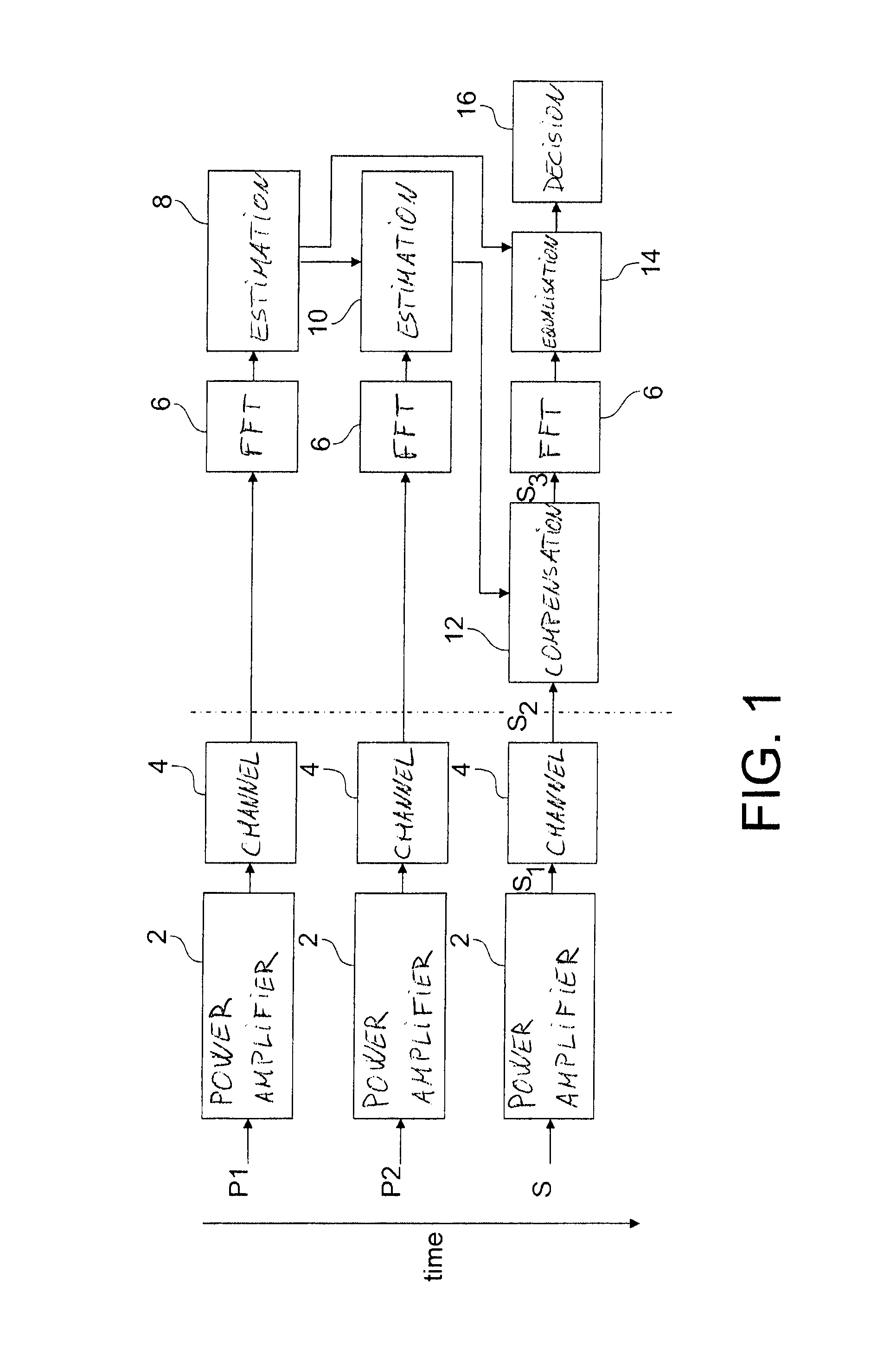
[0082]Reference is made first of all to FIG. 1 which shows a time-based operation of a method for the digital compensation of non-linearities in a communication system 300 according to a particular embodiment, in combination with FIG. 6 showing the communication system 300 comprising a receiver device 100, such as a base station. In this embodiment, the method is applied to a wireless communication system 300 with OFDM type modulation between a mobile terminal 200 and a base station 100. But an embodiment of the invention may also apply to other systems of the single carrier or ultra broadband type, between any transmitter and any receiver.

[0083]In the example in FIGS. 1 and 6, a power amplifier 2 found at the mobile terminal end 200 is considered as the single source of nonlinearities in the whole communication system 300. But an embodiment of the invention allows other sources of nonlinearities to be compensated in the communication system 300, at the transmitter 200 and / or receiv...


PUM


Abstract

A method for digital compensation of nonlinearities in a communication system that includes a transmitter, a transmission channel and a receiver, including: estimating the nonlinearities induced by the transmitter and / or the receiver, from at least one learning sequence received at the receiver and distorted by the nonlinearities, and compensating for the nonlinearities distorting a signal received at the receiver based on the estimating of the nonlinearities.

Description

TECHNICAL FIELD AND PRIOR ART[0001]The present application relates to a method for the digital compensation of nonlinearities in a communication system, and a receiver device implementing such compensation. The present application relates more particularly to the compensation of nonlinearities in a signal, amplified at transmission and / or at reception, and distorted by the nonlinearities of the amplifiers or active components present at transmission and / or at reception in the communication system.[0002]Nonlinear elements necessary for the transmission of information, such as power amplifiers or low noise amplifiers, are present in communication systems. Under the effects of the nonlinearities of these elements, a variable power signal transmitted in one of these communication systems is distorted, disturbing the reconstitution of the information carried by this signal at reception.[0003]For systems using large dynamic modulations, such as Universal Mobile Telecommunications Systems ...

Claims


Application Information

Patent Timeline
Patent Type & Authority Patents(United States)
IPC IPC(8): H04B7/00H04B1/16
CPCH03F1/3241H03F1/3258H03F3/24H04L27/261H03F2200/451
Inventor DEHOS, CEDRICSCHENK, TIMMORCHE, DOMINIQUE
Owner COMMISSARIAT A LENERGIE ATOMIQUE ET AUX ENERGIES ALTERNATIVES
Why Eureka
Try Eureka