Piezoelectric transformer driving device, cold-cathode tube inverter, cold-cathode tube driving device, and image forming apparatus

a driving device and driving device technology, applied in the direction of transit-tube circuit elements, machines/engines, cathode-ray/electron beam tube circuit elements, etc., can solve the problems of difficult to design a driving device for digital piezoelectric transformers and difficult to reduce the characteristic variation of piezoelectric transformers

Active Publication Date: 2012-05-08
OKI DATA CORP
View PDF5 Cites 7 Cited by
  • Summary
  • Abstract
  • Description
  • Claims
  • Application Information

AI Technical Summary

Problems solved by technology

(b): It is difficult to reduce the characteristic variation of the piezoelectric transformer due to its variation.
(c): It is difficult to design a digital piezoelectric transformer driving device, because the digital piezoelectric transformer driving device requires an oscillator having several hundred MHz to GHz for driving the piezoelectric transformer at the required frequency resolution.

Method used


Image

  • Piezoelectric transformer driving device, cold-cathode tube inverter, cold-cathode tube driving device, and image forming apparatus
  • Piezoelectric transformer driving device, cold-cathode tube inverter, cold-cathode tube driving device, and image forming apparatus
  • Piezoelectric transformer driving device, cold-cathode tube inverter, cold-cathode tube driving device, and image forming apparatus

Examples


first embodiment

[First Embodiment]

[0037](Configuration of Image Forming Apparatus)

[0038]FIG. 3 is a block diagram of image forming apparatus 1 using a power supply device according to the first embodiment of the invention.

[0039]Image forming apparatus 1 is a color electrophotographic image forming apparatus in this embodiment. Image forming apparatus 1 includes developing units 2K, 2Y, 2M, and 2C, image transfer unit (image transfer rollers 5K, 5Y, 5M, 5C, image transfer belt driving roller 6, image transfer belt driven roller 7, image transfer belt 8), fixing unit 18, paper cassette 13, hopping roller 14, and resist rollers 16 and 17. Developing unit 2K for black toner, developing unit 2Y for yellow toner, developing unit 2M for magenta toner, and developing unit 2C for cyan toner are detachably attached to the body of image forming apparatus 1. Developing units 2K, 2Y, 2M, and 2C respectively include photosensitive drums 32K, 32Y, 32M, and 32C, charging rollers 36K, 36Y, 36M, and 36C, supplying r...

second embodiment

[Second Embodiment]

[0138](Configuration of Second Embodiment)

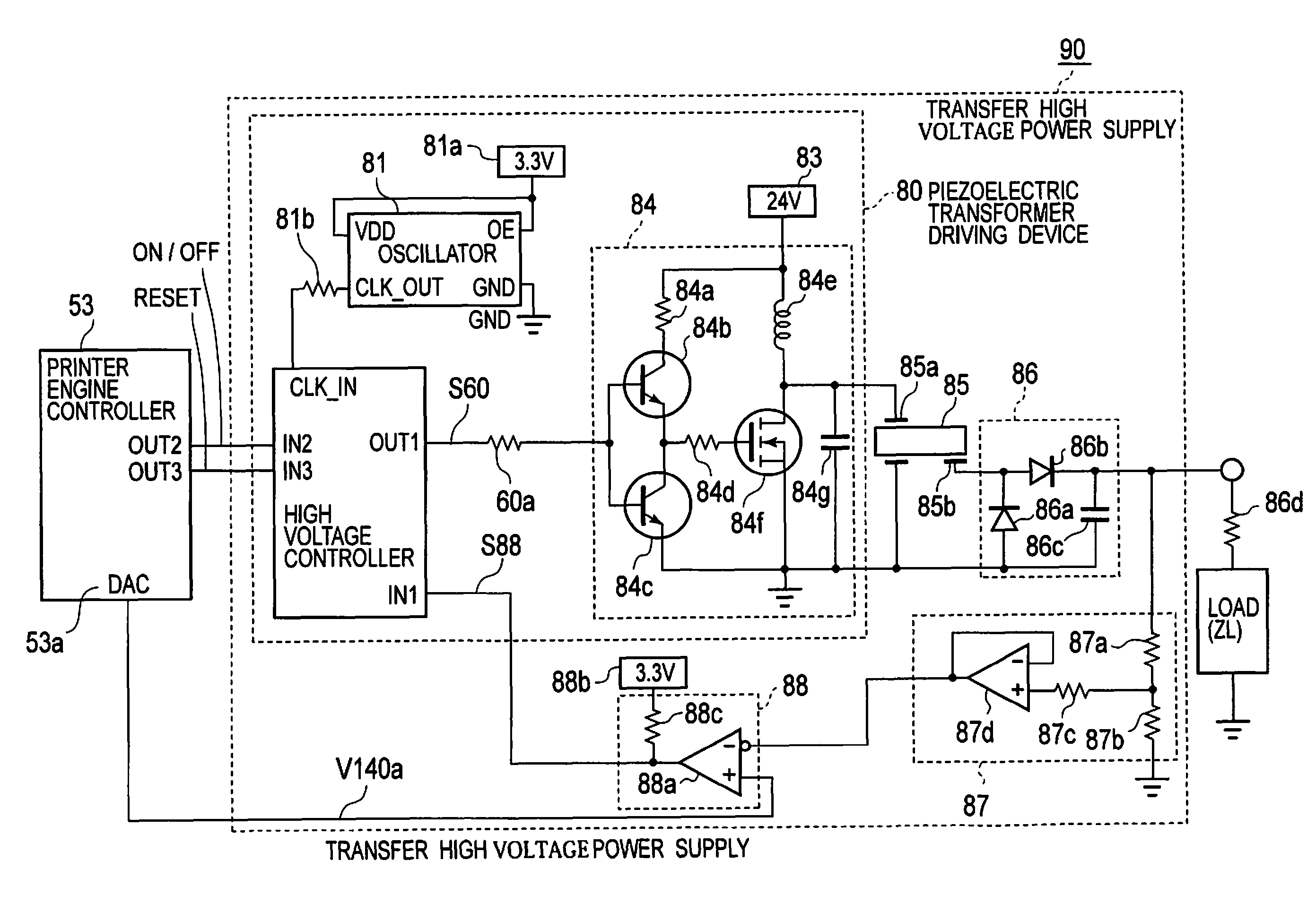
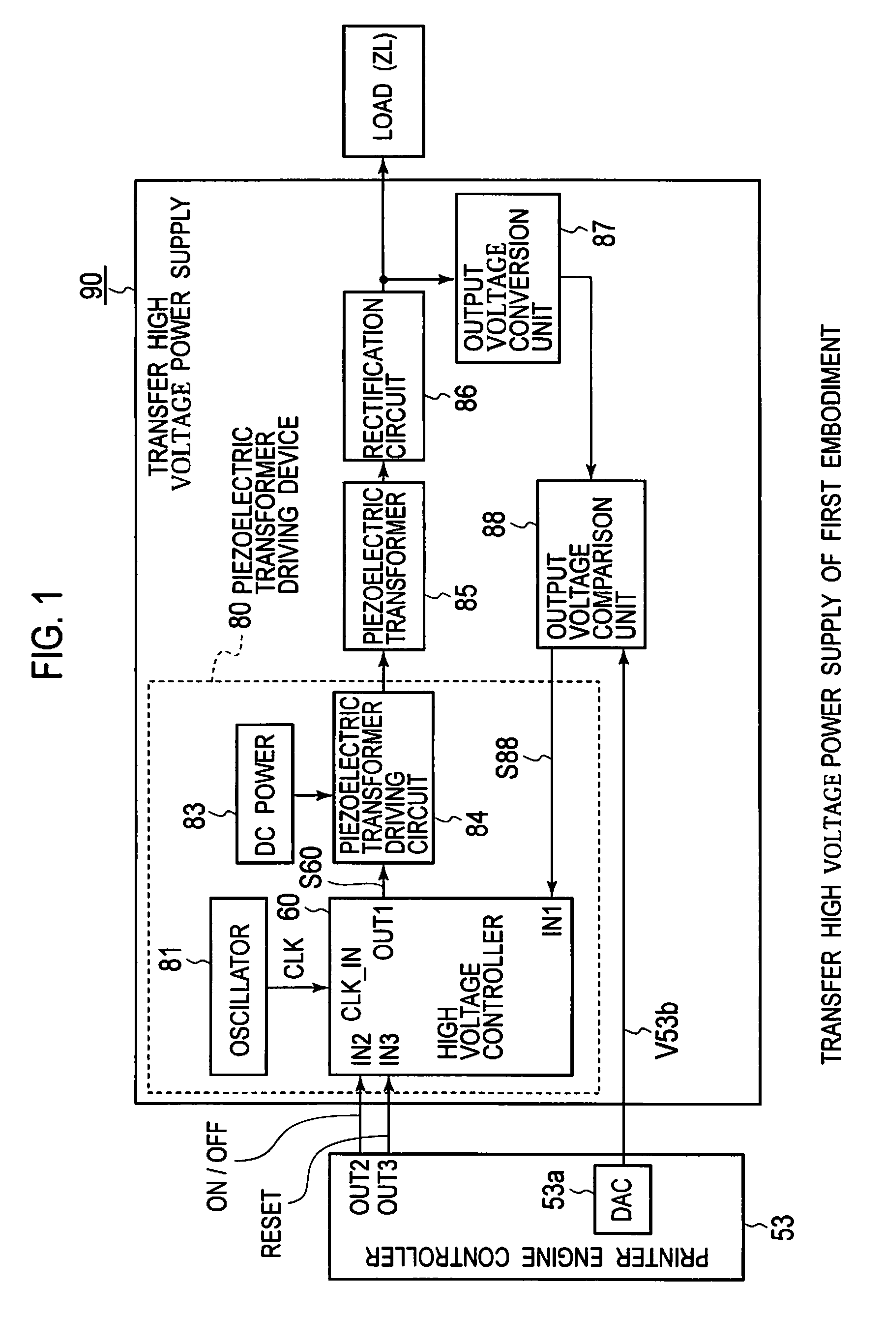
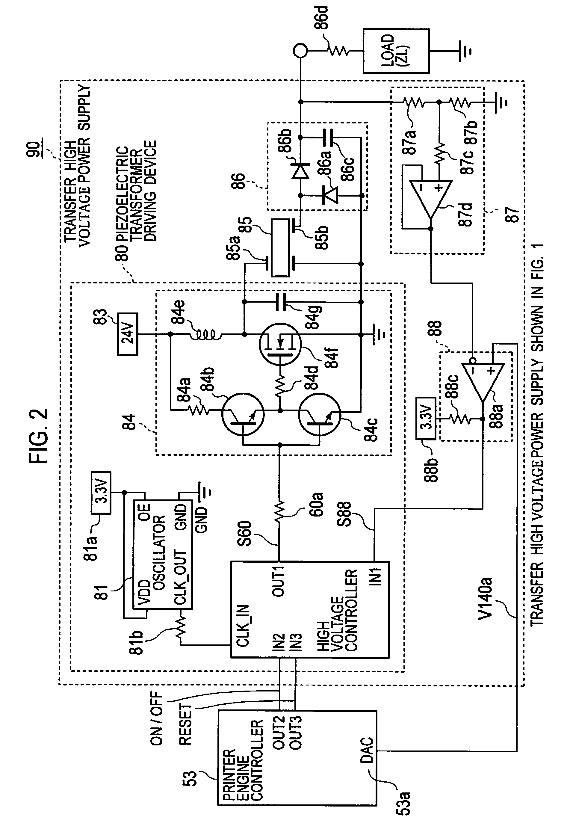
[0139]The second embodiment of the invention has the same configuration of image forming apparatus 1 shown in FIG. 3, the control circuit shown in FIG. 4, transfer high voltage power supply 90 shown in FIG. 1, and piezoelectric transformer driving device 80 shown in FIG. 2 as the first embodiment, and has a high voltage controller that has a different configuration from the first embodiment in piezoelectric transformer driving device 80.

[0140]FIG. 9 is a block diagram of a high voltage controller in a piezoelectric transformer driving device according to the second embodiment of the invention. In FIG. 9, the same configurations as those shown in FIG. 6 of the first embodiment are designated by the same reference numerals.

[0141]High voltage controller 60A of the second embodiment has 3-bit shift register 74 and arithmetic unit 71A having a different configuration or function from arithmetic unit 71 provided in high voltage ...

third embodiment

[Third Embodiment]

[0153](Configuration of Third Embodiment)

[0154]A third embodiment of the invention has the same configurations of image forming apparatus 1 shown in FIG. 3, the control circuit shown in FIG. 4, transfer high voltage power supply 90 shown in FIG. 1, and piezoelectric transformer driving device 80 shown in FIG. 2 as those of the first embodiment, and has a different configuration of high voltage controller in piezoelectric transformer driving device 80 from that of the first embodiment.

[0155]FIG. 11 is block diagram of a high voltage controller provided in a piezoelectric transformer driving device according to the third embodiment of the invention. In the third embodiment, the same configurations as in FIG. 6 of the first embodiment are designated by the same reference numerals.

[0156]High voltage controller 60B of the third embodiment has, instead of comparison unit 63-2, arithmetic unit 71 and error holding register 72 which are provided in high voltage controller ...


PUM


Abstract

A piezoelectric transformer driving device including: an oscillator; a frequency-divider outputting a pulse by dividing a clock signal from the oscillator by a frequency-divide ratio received thereto; a switching element driven by the pulse and intermittently applying a voltage to a primary side of a piezoelectric transformer; a frequency-divide ratio instructing unit holding a frequency-divide ratio instruction value of a real number having an integer part and an fractional part; a binarization unit binarizing the frequency-divide ratio instruction value into two different integer frequency-divide ratios and selectively outputting the frequency-divide ratios. The binarization unit adjusts an appearance ratio of the frequency-divide ratios such that an average of the frequency-divide ratios output from the binarization unit is equal to an average of the frequency-divide ratio instruction value.

Description

CROSS REFERENCE TO RELATED APPLICATIONS[0001]This application claims priority based on 35 USC 119 from prior Japanese Patent Application No. 2009-016766 filed on Jan. 28, 2009, entitled “piezoelectric transformer driving device, cold-cathode tube inverter, cold-cathode tube driving device and image forming apparatus”, the entire contents of which are incorporated herein by reference.BACKGROUND OF THE INVENTION[0002]1. Field of the Invention[0003]The invention relates to a piezoelectric transformer driving device operable to drive a piezoelectric transformer, a cold-cathode tube inverter and a cold-cathode tube driving device that are operable to drive a cold-cathode tube using the piezoelectric transformer driving device, and an electrophotographic image forming apparatus using the piezoelectric transformer driving device, the cold-cathode tube inverter, or the cold-cathode tube driving device.[0004]2. Description of Related Art[0005]A conventional power supply device used for an el...

Claims


Application Information

Patent Timeline
Patent Type & Authority Patents(United States)
IPC IPC(8): H05B37/02H01J29/96
CPCH05B41/2827
Inventor KOSAKA, TORUYAJI, MASAOHAGIWARA, AKIRA
Owner OKI DATA CORP
Why Eureka
Try Eureka