Apparatus, method, and program product for image processing

a program product and image processing technology, applied in image enhancement, color signal processing circuits, instruments, etc., can solve problems such as data encoding (e.g. compression) noise, and achieve the effects of reducing noise, suppressing excessive blurring of images, and reducing nois

Inactive Publication Date: 2012-05-08
SEIKO EPSON CORP
View PDF9 Cites 10 Cited by
  • Summary
  • Abstract
  • Description
  • Claims
  • Application Information

AI Technical Summary

Benefits of technology

[0007]An advantage of some aspects of the present invention is to provide a technology whereby noise can be reduced, while giving consideration to relationships among noise reduction, image blurring, and color components.
[0009]With this arrangement, since the strongest smoothing process is carried out on the first color difference component, excessive blurring of the image can be suppressed, and noise can be reduced as well. As a result, noise can be reduced while giving consideration to relationships among noise reduction, image blurring, and color components.

Problems solved by technology

Some examples are noise produced by the image capture element (e.g. a CCD) used to generate the image data; noise produced by the A-D conversion element that converts the analog data from the image capture element to digital data; errors in mathematic operations used to compute the tone values of the color components; and noise occurring with encoding (e.g. compression) of the data.
However, there has yet to be devised an innovation that gives sufficient consideration to interrelationships among noise reduction, image blurring, and color components in instances where colors of pixels are represented by multiple color components.

Method used


Image

  • Apparatus, method, and program product for image processing
  • Apparatus, method, and program product for image processing
  • Apparatus, method, and program product for image processing

Examples


embodiment 1

B1. Embodiment 1 of Smoothing Process Utilizing Block Noise Strength;

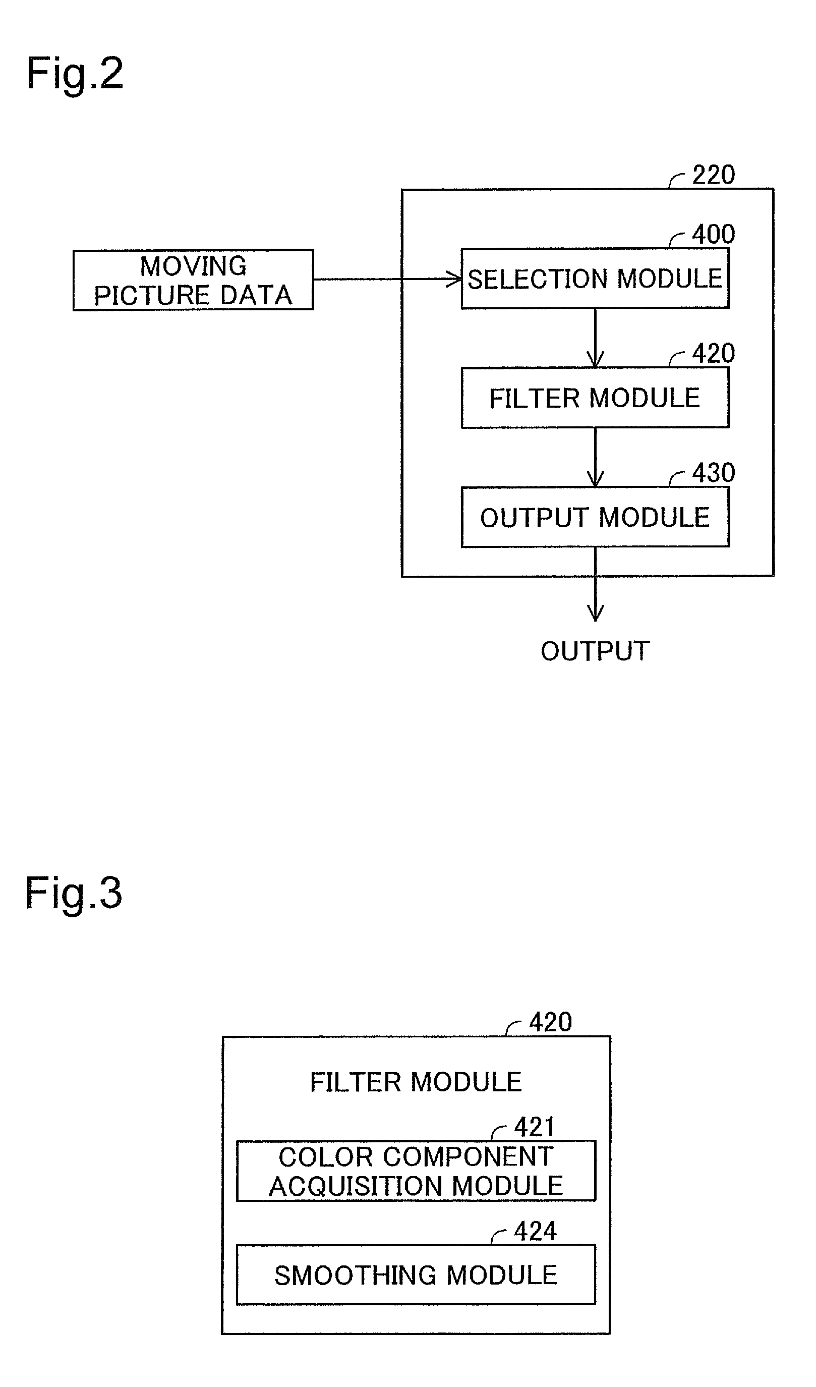
[0073]FIG. 5 is a schematic diagram of a picture. In this embodiment, a single picture PCT represents a rectangle image. Additionally, the single picture PCT have been split into a plurality of pixel blocks BLK of rectangle shape, with the data encoded on an individual pixel block BLK basis. These pixel blocks BLK are arrayed in lines respectively in the horizontal direction hr and in the vertical direction vt. In the embodiment, each pixel block BLK is a block of 8*8 pixels. The selection module 400 restores the frame image data by decoding the data of each individual pixel block BLK.

[0074]Various values may be employed for the pixel count in the horizontal direction hr and the pixel count in the vertical direction vt of the picture PCT. For a given image (subject) represented by the picture PCT, a larger pixel count of the picture PCT means that each single pixel block BLK represents a more detailed portion of th...

embodiment 2

B2. Embodiment 2 of Smoothing Process Utilizing Block Noise Strength:

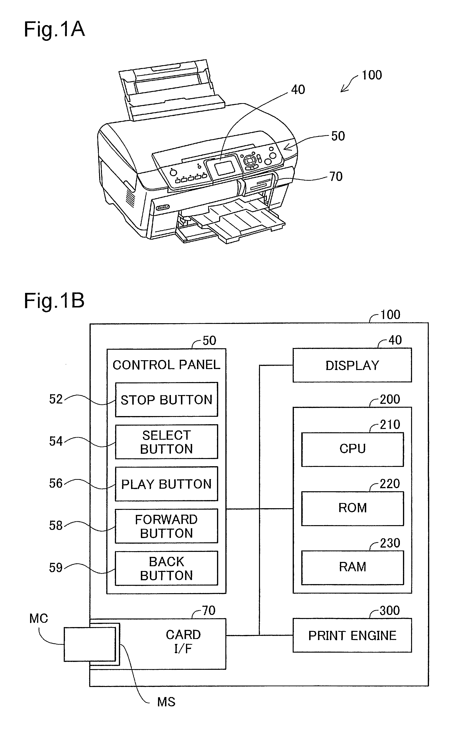
[0122]FIG. 20 is an illustration depicting an overview of another embodiment of the smoothing process. The only difference from the embodiment depicted in FIG. 17 is that the magnitude of smoothing becomes stronger as the pixel position within a pixel block become closer to the boundary line. The device configuration and process steps are the same as in the embodiment illustrated in FIGS. 1A-1B, FIG. 2, FIG. 9, and FIG. 10.

[0123]The drawing depicts an example of a smoothing level matrix SL. This 8*8 matrix SL indicates a smoothing level at each pixel position within a pixel block. In the example of FIG. 20, the level is set to any of levels 1 to 4. Higher levels mean stronger smoothing. Also, the level is set to a greater value with decreasing distance from the boundary line Bn, Be, Bs, Bw of the pixel block.

[0124]The drawing depicts the target image SI and the pixel block group BG similar to those in FIG. 11. The ...

embodiment 3

B3. Embodiment 3 of Smoothing Process Utilizing Block Noise Strength:

[0129]FIG. 21 is an illustration depicting an overview of yet another embodiment of the smoothing process. The only difference from the embodiment depicted in FIG. 17 is that the normalized strength calculated through interpolation depending on pixel position within the pixel block is used in place of the representative normalized strength αf. The device configuration and process steps are the same as in the embodiment illustrated in FIGS. 1A-1B, FIG. 2, FIG. 9, and FIG. 10.

[0130]FIG. 21 depicts an overview of the smoothing process of a given target pixel PXx. In this embodiment, the smoothing module 424 (FIG. 9) calculates a horizontal normalized strength αph1 through linear interpolation of the horizontal direction hr, and a vertical normalized strength αpv1 through linear interpolation of the vertical direction vt.

[0131]The horizontal normalized strength αph1 is calculated from the left normalized strength αw of...


PUM


Abstract

From the target image data, a luminance component, a first color difference component, and a second color difference component which represent color of respective pixels are acquired; and a maximum magnitude smoothing process is carried out on the first color difference component.

Description

CROSS-REFERENCE TO RELATED APPLICATIONS[0001]The present application claims the priority based on Japanese Patent Application No. 2007-213965 filed on Aug. 20, 2007, the disclosure of which is hereby incorporated by reference in its entirety.BACKGROUND[0002]1. Technical Field[0003]The present invention relates to an apparatus, a method, and a program product for image processing.[0004]2. Description of the Related Art[0005]Colors of pixels of image data can be represented using various color components. For example, the three components of R (red), G (green), and B (blue), or the three components of Y (luminance), Cb, and Cr (color difference), might be used. Noise of various kinds may be included in tone values of such color components. Some examples are noise produced by the image capture element (e.g. a CCD) used to generate the image data; noise produced by the A-D conversion element that converts the analog data from the image capture element to digital data; errors in mathemat...

Claims


Application Information

Patent Timeline
Patent Type & Authority Patents(United States)
IPC IPC(8): G06K9/00
CPCH04N1/58G06T5/002G06T5/20G06T2207/10024G06T2207/20192
Inventor SHIRAISHI, SHINICHI
Owner SEIKO EPSON CORP
Why Eureka
Try Eureka