Heat sink for a thermally efficient busway joint pack

a busway and joint pack technology, applied in the direction of butt joining bus-bars, connection contact member materials, basic electric elements, etc., can solve the problems of overall thermal performance, direct influence on the required size of the busway and/or the size of the phase-conductors, and management of the rise in temperature, so as to reduce the internal temperature of the joint pack

Active Publication Date: 2012-05-15
SCHNEIDER ELECTRIC USA INC
View PDF18 Cites 18 Cited by
  • Summary
  • Abstract
  • Description
  • Claims
  • Application Information

AI Technical Summary

Benefits of technology

[0005]The present disclosure is directed to providing a heat sink for a thermally efficient busway joint pack. The thermally efficient busway joint pack is configured to passively transfer thermal energy or heat from its core to the outside of an exterior housing of the busway such that the thermal energy is lost or transferred to the surrounding environment, which reduces the internal temperature of the joint pack. The joint pack includes a pair of opposing conductive phase connector plates defining a space therebetween for

Problems solved by technology

A common problem in busway systems is the management of the rise in temperature of the busway system within the busway joint pack.
A rise in temperature within the busway joint pack limits the overall thermal performance of the busway system, which directly affects the required size of the busway and/or the size of the phase-conductors.
Using larger phase-conductors to accommodate the rise in temperature at the

Method used


Image

  • Heat sink for a thermally efficient busway joint pack
  • Heat sink for a thermally efficient busway joint pack
  • Heat sink for a thermally efficient busway joint pack

Examples


Embodiment Construction

[0019]Although the invention will be described in connection with certain aspects and / or embodiments, it will be understood that the invention is not limited to those particular aspects and / or embodiments. On the contrary, the invention is intended to cover all alternatives, modifications, and equivalent arrangements as may be included within the spirit and scope of the invention as defined by the appended claims.

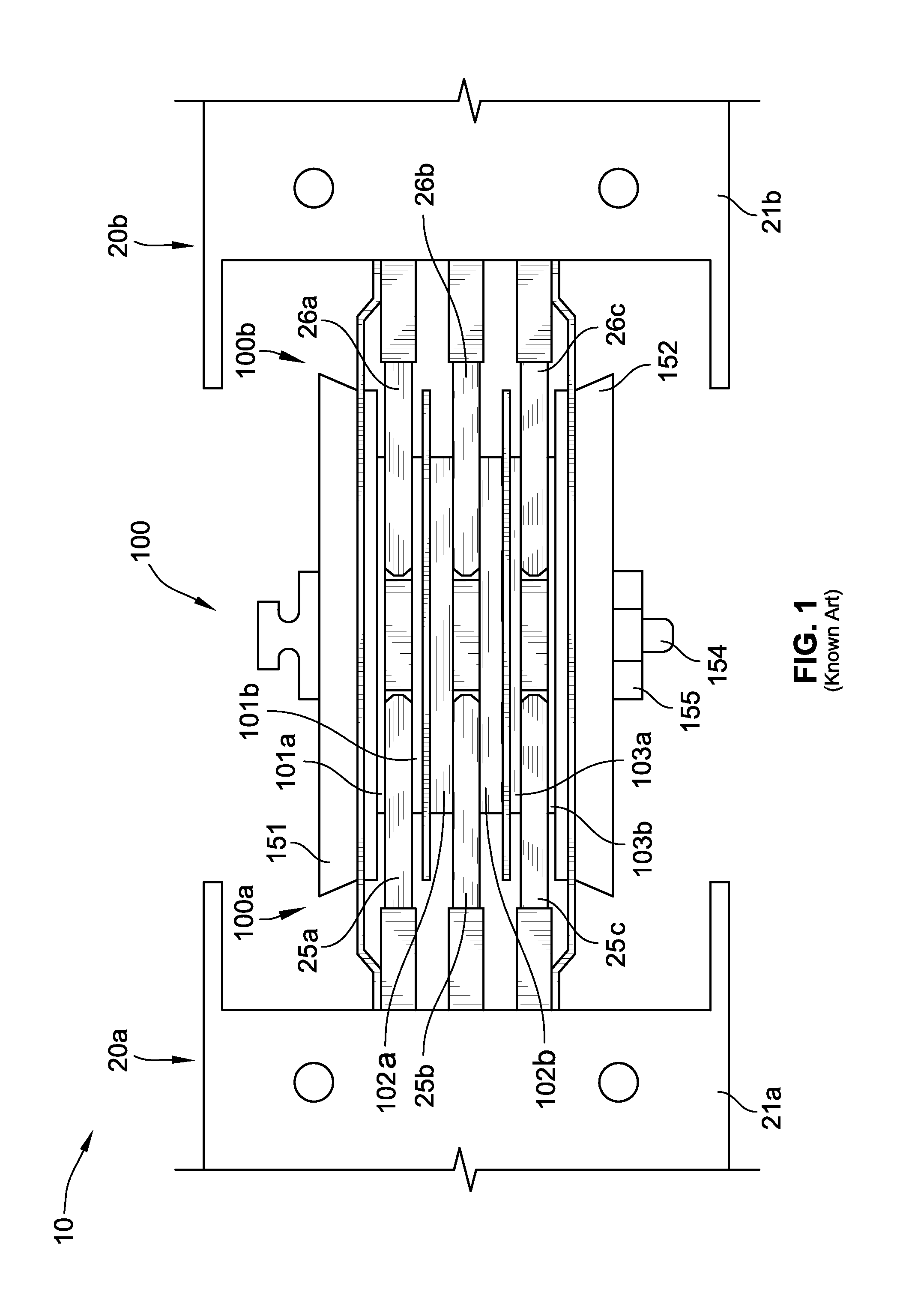
[0020]Referring to FIG. 1, an exemplary known busway system 10 is shown for general exposition of joint pack parts and the environment of the present invention. The busway system 10 includes a joint pack 100, with its side panels removed for ease of view interior parts, a first busway section 20a, and a second busway section 20b. The first and the second busway sections 20a,b are three pole busways and / or three phase busways. The first busway section 20a includes a busway housing 21a and three phase-conductors 25a-c. Each of the phase-conductors 25a-c are electrically insul...


PUM


Abstract

A busway joint pack for joining busway conductor sections has a heat sink assembly with an interstitial heat sink portion sized to fit between its connector plates; an exterior heat sink portion projecting beyond the exterior surface of a side panel of the joint pack; with the interstitial heat sink portion having thermal conduction to the exterior heat sink portion; to attain cooler operation. The heat sink may include thermally conductive dielectric materials or metals, or both, or other thermally conductive materials used with the thermally conductive dielectric materials.

Description

FIELD OF THE INVENTION[0001]The present invention relates generally to electrical distribution equipment and, more particularly, to thermally efficient busway joint packs.BACKGROUND OF THE INVENTION[0002]A busway system is a prefabricated modular electrical power delivery system which typically includes two or more busways, one or more busway joint packs, and may include a plurality of plug-in units. Each busway includes one or more phase-conductors and a housing. For example, in a three phase system, the busway can include three live phase-conductors or three live phase-conductors and one neutral-conductor, depending on the type of system architecture being employed. If required, various plug-in units or electrical components can be directly connected to one or more plug-in connection sites spaced along the busways to draw power. Each busway joint pack is used to physically and electrically connect two sections of busway together.[0003]A common problem in busway systems is the mana...

Claims


Application Information

Patent Timeline
IPC IPC(8): H01R4/60
CPCH02G5/007H02G5/10
Inventor DOZIER, STEVEN WAYNEWILLIFORD, MATTHEW A
Owner SCHNEIDER ELECTRIC USA INC
Why Eureka
Try Eureka