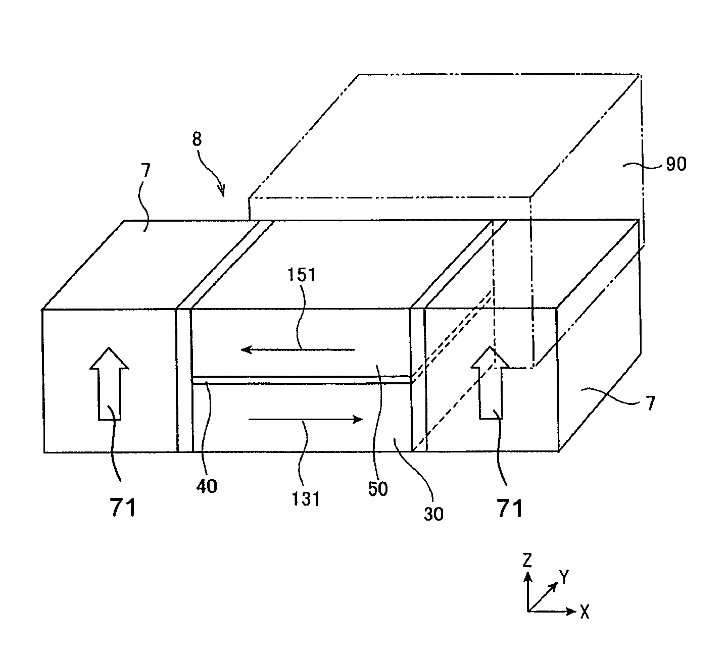
Magnetoresistive effect element in CPP structure and magnetic disk device

a magnetic disk and effect element technology, applied in the field of magnetic disk device and effect element magnetoresistive effect element, can solve the problems of reduced heat dissipation efficiency, limited reliability of operating current in conventional structure, and difficult narrowing of substantial reading width

Active Publication Date: 2012-05-15
TDK CORPARATION
View PDF11 Cites 34 Cited by
  • Summary
  • Abstract
  • Description
  • Claims
  • Application Information

AI Technical Summary

Problems solved by technology

A problem existed that the operating current was limited in the conventional structure in terms of reliability because the heat dissipating efficiency decreased as the area decreased.
However, with respect to the high recording density of 660 Gbpsi or more in the future, even though the width of the MR element is narrowed, there was an indication that the substantial reading width is hard to be narrowed.
When the conventional technology is used, the photo-width (or width of a pattern made with a photoresist) of 20 nm or less is required and it is very hard to manufacture in view of the process technology.
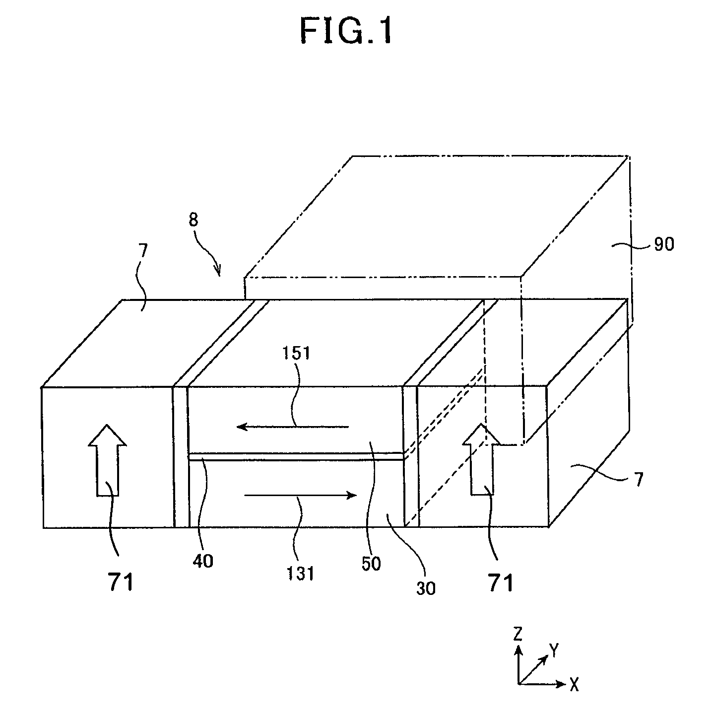
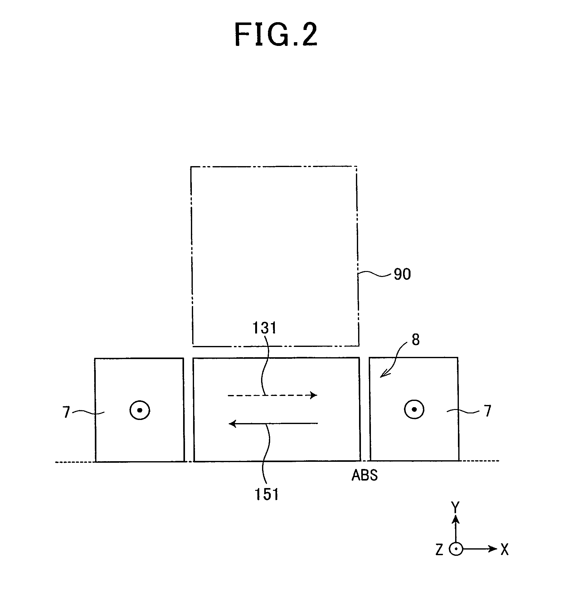
When the magnetic field in the cross direction to the element (mainly the recording magnetic field of the adjacent track) is applied to the DFL element structure, a magnetization direction regulation state (an initial magnetization direction state tilting about 45 degrees relative to the track width direction (initial state)) of the two free layers is broken, i.e., a behavior balance is broken, and there is a possibility that the DFL element cannot operate properly.

Method used


Image

  • Magnetoresistive effect element in CPP structure and magnetic disk device
  • Magnetoresistive effect element in CPP structure and magnetic disk device
  • Magnetoresistive effect element in CPP structure and magnetic disk device

Examples


specific experimental embodiment

[0168]A description of a specific experimental embodiment is given below for the MR element according to the present invention in order to explain the invention in more detail.

embodiment 1

Fabrication for Embodiment 1 Sample

[0169]A MR effect layer, which functions as a DFL element and is configured with a lamination structure as shown in Table 1 below, was formed.

[0170]In the lamination structure of Table 1 below, a read gap length corresponding to a main part of the sensor is 14.6 nm that was a total layer thickness of the first antiferromagnetic coupling intermediate layer (300′), the first ferromagnetic layer (50), the nonmagnetic intermediate layer (40), the second ferromagnetic layer (30), and the second antiferromagnetic coupling intermediate layer (500′). After layers were formed, the lamination structure was processed by a heat treatment at 250° C. for three hours in a magnetic field of 1 tesla (T).

[0171]

TABLE 1Layer Layer Lamination StructureMaterialThickness (nm)Upper Main Shield Layer (5a)NiFe1000Antiferromagnetic Layer (5b)IrMn7.0Upper Exchange-Coupling CoFe1.0Shield Layer (5c)NiFe8.0CoFe1.0Ru0.8CoFe1.0NiFe8.0CoFe1.0Second Antiferromagnetic CouplingRu0.8In...


PUM

PropertyMeasurementUnit
read gap lengthaaaaaaaaaa
widthaaaaaaaaaa
total thicknessaaaaaaaaaa

Abstract

An MR element in a CPP structure includes an MR part configured with a nonmagnetic layer, a first ferromagnetic layer that functions as first free layer and a second ferromagnetic layer that functions as a second free layer, and first and second ferromagnetic layers are laminated to sandwich the nonmagnetic intermediate layer, and a sense current flows in a lamination direction of the MR part, an orthogonalizing bias function part, which influences a substantial orthogonalization function for magnetization directions of the first ferromagnetic layer and the second ferromagnetic layer, is formed on the rear side the MR part, side shield layers are disposed on both sides in the width direction of the MR part, the side shield layers are perpendicular magnetized layers with a magnetic shield function, and magnetization directions of the perpendicular magnetized layers are in an orthogonal direction that corresponds to the thickness direction.

Description

BACKGROUND OF THE INVENTION[0001]1. Field of the Invention[0002]The present invention relates to a magnetoresistive effect element (MR element) in a current perpendicular to plane (CPP) structure that detects magnetic field intensity as a signal from a magnetic recording medium, and so on, a thin film magnetic head with the MR element, and a head gimbal assembly and a magnetic disk device that have the thin film magnetic head.[0003]2. Description of Related Art[0004]In recent years, with an increase in the high recording density of magnetic disk drives (HDD), there have been growing demands for improvements in the performance of thin film magnetic heads. For a thin film magnetic head, a composite type thin film magnetic head has been widely used; it has a structure where a reproducing head having a read-only magnetoresistive effect element (hereinafter, magneto-resistive (MR) element) and a recording head having a write-only induction type magnetic conversion element are laminated t...

Claims


Application Information

Patent Timeline
Patent Type & Authority Patents(United States)
IPC IPC(8): G11B5/39
CPCB82Y10/00B82Y25/00G01R33/098G11B5/3909G11B5/3912G11B2005/3996
Inventor KAWAMORI, KEITATSUCHIYA, YOSHIHIROMIYAUCHI, DAISUKEMACHITA, TAKAHIKO
Owner TDK CORPARATION
Why Eureka
Try Eureka